Nitrogeno25
|
| posted on 11/8/05 at 03:50 PM |

|
|
Engine mounts reinforcement
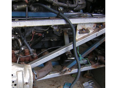
Hi, I'm the engine mounts stage and want to reinforce this section to be on the safe side. I see modifications that join G1/G2 to J1/J2 where
the engine mounts should be. I was thinking if adding a member from G1/G2 to where J1/J2 join Hs would be a good idea?
Thanks
Gonzalo
|
|
|
|
|
niceperson709
|
| posted on 11/8/05 at 10:59 PM |

|
|
Hi Mate
given that the engine mountwill be 3mm plate that would be a bit unnecessary but you would gain more from extra triangulation of the engine bay mine
has an extra "R " tube on the left side and extra diagonals on the sides and the front trapezoid has more to .
The engine bay is a bit to flimsy and you will make the whole car more rigid by re inforcement . see my picture[pg=]
Best wishes IAIN
life is not the rehearsal , it's the show so don't sit there thinking about it DO IT NOW
http://iainseven.wordpress.com/

|
|
|
niceperson709
|
| posted on 11/8/05 at 11:02 PM |

|
|
anothe photo [pg=] [pg=]
Best wishes IAIN
life is not the rehearsal , it's the show so don't sit there thinking about it DO IT NOW
http://iainseven.wordpress.com/

|
|
|
NS Dev
|
| posted on 12/8/05 at 07:17 AM |

|
|
I have done the same with the extra "R" tube, but I've made it bolt in, so it can come out to make extracting the engine a bit
easier.
|
|
|
MikeRJ
|
| posted on 12/8/05 at 02:15 PM |

|
|
quote:
Originally posted by Nitrogeno25
Hi, I'm the engine mounts stage and want to reinforce this section to be on the safe side. I see modifications that join G1/G2 to J1/J2 where
the engine mounts should be. I was thinking if adding a member from G1/G2 to where J1/J2 join Hs would be a good idea?
Thanks
Gonzalo
Personaly I think this is an excellent idea, I'm certainly building this into mine.
The problem is not the 3mm engine mounting plates, but the fact that the entire weight of the engine is being supported in the middle of the fairly
long G and F tubes, putting a huge bending strain on them. And bend they certainly do! When I originaly put a Pinto in mine I could see these tubes
visibly move as I lowered the engine onto it's mountings.
By putting an upright member from F to J and splitting the TR diagonly into two shorter pieces the engine mountings are made far stronger. The only
thing you have to watch out for is the new upright section potentialy fouling your exhaust exit.
|
|
|
niceperson709
|
| posted on 12/8/05 at 11:12 PM |

|
|
I just want to say that if you want to add extra tube to the structure you would be better off adding diagonals as these will add mor to the space
fram e stiffness than verticals . I have added an extra diagonal on both sides of the engine bay and the have a suporting role for the engine mount
area as well
 
Rescued attachment Tri.jpg
Best wishes IAIN
life is not the rehearsal , it's the show so don't sit there thinking about it DO IT NOW
http://iainseven.wordpress.com/

|
|
|
MikeRJ
|
| posted on 13/8/05 at 12:48 AM |

|
|
Iain,
The method I described (and which several people have already used) does incorporate diagonals. The long diagonal that triangulates the sides of the
engine bay (TR1 and TR2 in the book) is replaced by two shorter diagonals and an upright piece as in the following diagram (red is location of engine
mount).

I suspect that idealy the diagonals would meet at the engine mount for the highest strength, but then the digaonals will not join up with the
diagonals in the preceding chassis sections which would probably be a worse compromise overall.
|
|
|
Nitrogeno25
|
| posted on 13/8/05 at 03:29 AM |

|
|
First, thank all for your replies.
niceperson709, I made exactly the same (except I used round tubes) but I think of adding an extra member on the "other" direction, from
the top of tube H (where J meets F) to the engine mount at G.
|
|
|


