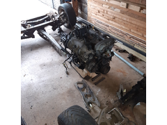

RemainsofMX-5donor

This project is now reaching the stage of "the end of the beginning", so time to start posting...
Progress to date:
Garage cleared of all non "Car" stuff.
Bought relevant books including (of course) Ron Champions Book, suspension design (etc, etc).
Downloaded IVA handbook and have spent many hours going over the demands of the regulations.
Downloaded publicly available photos of target car and similar cars that project car will be based on.
Donor vehicle (Mazda MX-5 Mk1 MOT failure due to rotten sills and associated structures) SORN'd
Donor vehicle dismantled using: Goggles, Strong Gloves, Old clothes, Steel capped boots, Metric Socket Set, 12 hacksaw blades, Cold Chisel and general
toolbox (screwdrivers, pliers etc). Many photos taken during dismantling, VIN plates and chassis stamping have been retained.
Wiring looms labelled and boxed with ECU.
Fuel tank and Donor bodywork cut into chunks and disposed of at local recycling centre (VIN plates kept).
Engine/Gearbox assembly placed on home made trolley for movement around garage.
Anything needed for new car has been labelled and stored in boxes, everything else has gone for recycling or in the bin.
Obtained build table wood and ply.
Rear sub-frame dismantled, lower rear wishbone to hub bolts were "frozen" solid so had to be cut/drilled out and hub mounting holes
cleaned.
Bought 24 metres of 25mm square/round 2mm wall mild steel tubes for basic chassis/frame.
Bought welder, welding helmet, welding gloves, angle grinder, files.
Planned stages over next 3 months:
1. Depower steering rack.
2. Dismantle front sub-frame, using engine mounting holes to construct jig for engine mounts onto frame.
3. Complete balsa wood (1/8 scale) model of new car space frame setting out major components and checking form, fit and clearances.
4. Bodywork to be modelled in card glued to balsa wood frame.
5. Optimise balsa wood model for maximum torsional stiffness at lowest number of elements.
6. Start construction by laying out and welding up initial frame components.
Known Challenges:
Remoting the gear lever change mechanism - various solutions exist but resources are limited.
Mounting radiator 90 degrees rotated, leaning back to clear nose height.
Retractable light units so can have "clean" lines when not on public road.
Constructing small fuel tank and associated fuel pipework.
Updates - will be provided as work proceeds.....
Donor components laid out prior to final dismantling for check measurements..


RemainsofMX-5donor
Sound like a great project. I note from your listing you are Bristol based - I'm Yate. Would love to take a look from time to time as you make progress...
Nice project, I love the proposed car style.
On your list you failed to add treatment for project OCD…
Lovely looking car. not dissimilar to the Mazda based Alfa lookalike kit that's available. Are you intending to keep as close as poss to the original, ie single seat or "inflate" it a bit so you can get 2 side by side?
Looking like a great project. Love the look of the car.
Forum rules :- lots of updates and photos please 
Nice looking car!
I'm sure you're aware of the rules on open wheel cars, but if not then read up on them as there's limited places you can use such cars.
quote:
Originally posted by nick205
Nice looking car!
I'm sure you're aware of the rules on open wheel cars, but if not then read up on them as there's limited places you can use such cars.
Putting "builder" but only thing being built at the moment is the balsa wood model!
Sanzomat : Cheers, good to hear from you, yes will let you know as project proceeds.
Snapper : Thanks for the feedback and good to hear from you.
Russbost : Many thanks for your interest. Aim is Single seater to maintain close to the proportions of the "original" but am filleting the
design in length and height around the engine bay to permit easier access to engine, aim is to finish balsa model this month. Problem with the
"alfa" based kit is that it is a kit and costs money and I am aiming to see what can be built at minimum cost. Donor car was
"free" as cost me £1,500 and then ran for 3 years before failing MOD. My ethos across the project is minimum cost, For example the build
table cost £10 for the screws and other fitments to be able to put together soon the seasoned 4in by 2in timbers that a builder kindly provided for
free from his skip. Another builders skip provided 4 sheets of 8ft by 4ft structural timber sheets for the table surface. The only resource I am not
limited in is time.
Nick205 : Many thanks for your warning. Aim is to build road legal as will not be driven on circuits. Looking to have "conformal" black
mudguard on black tyres so hopefully from a distance mudguards will not be overtly visible.
Noted - if mudguards are planned then that covers the issue.
I hope your going to fit a substantial roll bar as crashes in these vintage style machines are scary. They were mad in those days,
Hi Mr Whippy. Yes you are correct will need substantial roll over protection, more than just a 25mm 1.6mm thick tube roughly bent to shape round a
tree trunk. Problem I have is no tube bending equipment. Elsewhere on the "Net" some enterprising individual constructed a stainless steel
roll over from this type of tube and then bolted it to their car chassis:
Bike Stand
[Edited on 10/1/22 by Prof_Cook]
quote:
Originally posted by Prof_Cook
Elsewhere on the "Net" some enterprising individual constructed a stainless steel roll over from this type of tube and then bolted it to their car chassis: Bike Stand
[Edited on 10/1/22 by Prof_Cook]
Monthly update - So I reworked paper design for chassis quite a few times, now moved to balsa model, see linked file:
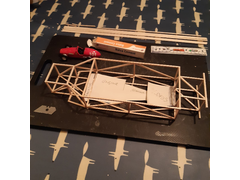

Balsa Chassis 43m
Now when scaled up (1:8) this results in total of 43m of chassis tube (at 2.04kg/m for 3mm wall worst case = 87.7Kg chassis weight. Probably another
10m for wishbones and the "hoops" to carry the bodywork above the chassis rails. There still seems to be space (even for the stock MX-5
radiator) for the major donor components while allowing sufficient space for the driver, (but still to remote the gear change). Meanwhile clear space
in the garage had to be surrendered for a week to carry out a service on a "Mercedes" 6v electric little car left at the side of the road
for free - got it working after 1 day and now out of garage into garden. So have started laying out build table wood and sawing/drilling same ....
[Edited on 7/2/22 by Prof_Cook]
Received in post, so another "encouragement" to get the project done....now got to keep eyes open for a stamping set.
when I first saw this, I thought, Moss Monaco...
Walk the dog each day for 2 miles locally. Amazing what you find lying in the road. Hopefully I have enabled someone to escape a puncture through
picking up stuff for my parts bin and my toolboxes. Of the stuff in the picture (found over 6 weeks), the top left corner goes to the parts bin, the
top right goes into my toolboxes while the stuff on the bottom piece of wood goes to metal recycling at the local tip.
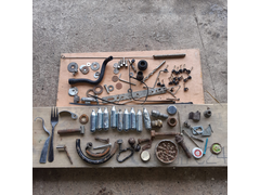

Stuff_found_on_road_side
[Edited on 27/2/22 by Prof_Cook]
Might get a few funny looks when you drop off those laughing gas cylinders - obviously the recreational substance of choice for your local youths
Build table completed, first steels cut, job this week is to mark up build table for all bottom rails and then keep cutting steels and clamping them
in position ready for welding. Will be offering up various components before welding rails to ensure everything fits.
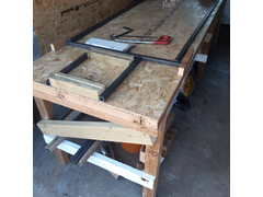

Description
Need to go round the local skips and get some 1in square timber for the clamps.
[Edited on 1/4/22 by Prof_Cook]
Build own sportscar and race it £17.93
Power drill £24.79
Drill bits £10.00
Welding gloves £6.05
Hacksaw blades £9.80
Safety goggles £11.07
Files £10.99
6in square £10.75
Build Avon Sportscar book £17.19
Auto darkening welding helmet £22.99
Welding magnets £20.60
Cordless drill £26.58
Metal cutting discs £6.00
Angle grinder £33.95
Safety impact goggles £3.00
Arc welder £56.75
Total £288.44
Various other books given as Christmas presents.
[Edited on 1/4/22 by Prof_Cook]
Balsa cement £3.49
Balsa wood for model £6.90
Build table screws and long drill bits £9.25
Steels £219.96
Welding electrodes £7.00
Total to date £246.60
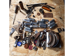
Cleared space from build table to photograph last 6 weeks finds out while walking the dog. Some sockets (17mm and 8mm) and long electrical screwdriver
and a few pence. Lots of rubbish for the metal recycling bins. Pity the gas cylinders arent worth anything. Now back to marking up build table and
cutting steel.

Findsfromroadside
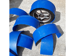
Out walking the dog last night, found large PVC drum at roadside with sign saying "FREE". Cut it up this morning as just the right size for
cyclewing blanks. Slow time job for end of build will be to sort out metal stays to mount them onto the wheel spindles and hot wire cutting tool to
produce clean edges. Also will need painting black.

Cycle wings blanks
[Edited on 11/4/22 by Prof_Cook]
A cunning plan indeed!
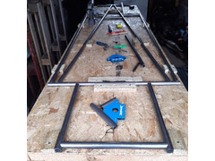
Project as at end April 2022 - too cold to work in the garage today.

End of April 2022
Challenging retirement project has been delayed a little due to contracting COVID-19. Luckily (!) only extreme tiredness. Have managed to get back
into the garage and back to cutting and shaping steel tube.
Got the engine mounts cut out of the old front sub-frame and offered up to a cross-tube ready for future welding. Took a week to get the cross tube
into the right location to ensure the engine is in correct location.
Now I have a growing pile of off-cuts it has been time to get the arc-welder, gauntlets, overalls, steel toe capped boots and welding helmet out and
start practising welding. Another delay as the battery in my helmet had died so had to wait till a certain on-line supplier got a pack of 5 batteries
out to me.
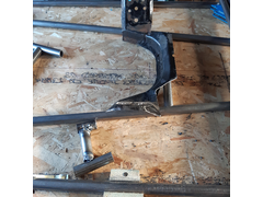
Today was first time trying to weld for over 40 years. Managed to strike arcs and place a few tack welds onto the test piece seen in the bottom of the
below photo, set current low to start off with. Top of the test piece was 45 amps with pre-heating from a Bosch hot air gun and this cant be broken
even with heavy hammering. Bottom of test piece was 55 amps without pre-heating, broke when cleaning off the crusty bits. Got a lot more
self-training on welding to do before I start welding the frame.

Starting to practice welding
[Edited on 4/7/22 by Prof_Cook]
Progress is still being made but slower than I would hope, but still posting updates monthly!
Good news : No more money spent.
Bad news : "Tack" welding of lower frame rails still only almost complete due to need to reweld quite a few of the welds as not good enough,
also hand cutting and filing ends of tubes with fish-mouths and fitting the tubes together takes longer than planned. So still got to complete lower
rails asap so I can lift them off the build table and start welding upper frame rails, and then tack together with uprights. Then to seam weld and
start welding major brackets (radiator) etc onto frame.
[Edited on 10/8/22 by Prof_Cook]
Stuff found at side of road while walking dogs.
Top left for parts bin. Top right for toolbox. Bottom stuff for local recycling bin.
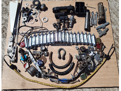

Stuff
I wonder who lost the morse taper drill sleeve?
It's an unusual thing to find at the side of the road...it'd make a mess of your windscreen if it bounced!
Retirement project continues to progress:
Good News
1. No money spent.
2. My welds continue to improve.
3. Lower frame rails tack welded together and didn't fall apart when removed from the jig.
4. Lower frame rails weigh only 14.3Kg
5. Started to cut and file the tubes for the much simpler top rails and then it be the uprights
Bad News
1. Progress still not as fast as originally planned but at least progress is being made.
Target car weighed 560Kg and with an engine power of 172BHP the driver enjoyed performance of some 307BHP/Tonne.
My donor car engine BHP was 105BHP so using that figure I need my car to weigh some 350Kg:
Engine BHP 105
Weight (Kg) 350
BHP/Tonne 300
So Target is 350 Kg
The following is my current weight allocation for each component:
Frame 50 (simpler than original design)
Engine 123 (no a/c or power steering)
Gearbox 36
Differential 26
ECU and Loom 5
Radiator 10
Steering Rack 10
Steering Wheel 10
Seats 15
Fuel Tank 10 (would limit range to ~60miles so would prefer 20Kg)
Hubs, wheels 55
350Kg
This is my first pass and I am sure I have forgotten something which will mean weight reduction will be needed, or the BHP/Tonne will drop. Loom
still to be rewired, radiator, Hubs/wheels still to be weighed, above figures are guess at this time....
[Edited on 6/9/22 by Prof_Cook]
How much do the lights weigh?
If you're looking to build to a weight, start counting the grams from the start.
Many thanks pigeondave
I overlooked lights which now need to be added to weight budget. Have ditched donor lights. Am keeping eye on certified lights on certain on-line
store to get smallest/lightest possible.
[Edited on 6/9/22 by Prof_Cook]
Nice project! On the power to weight ratio side, the MX5 lump is quite tuneable which should help if you go over your weight budget. Or turbo it and
get well over the 170hp you mentioned 
I'm also in Brizzle BTW, so yell if you ever need a hand. Can't guarantee I'll be able to, but the offer's there!
quote:
Originally posted by pigeondave
How much do the lights weigh?
If you're looking to build to a weight, start counting the grams from the start.
End of September Update
Good News
1. No more money spent, but need to get some more 25mm 2mm wall tubing so watch this space..
2. Folding work bench was showing signs of strain so now I have built a workbench which now sits between front of build table and chest freezer at
back of garage. Workbench has been built of "skip" wood (4in by 2in lumber) and some 25mm square 3 mm think walled tubing.
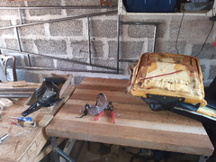

Workbench
3. Neighbour having garage clearout before building an extension so I was lucky to pick up some tools which were out on their drive for anyone to
take away, including the red handled compound action cutters you can see in the workbench photo. While picking these up the neighbour came out with
another cardboard box full of stuff and got a metal tin with about 60 different sized metal drill bits.
4. Compound action cutters made it an easy job to cut the steel rings which fixed the seat covers to the seat pan and back. Only took 5 minutes (wore
safety glasses, gloves and covered the rings with cloth while cutting) and now modifying seat pan to reduce depth of seat pan which should enable seat
to be fitted lower in the car while still clearing the prop shaft and associated restraint cage.
Bad News
1. Getting distracted from frame build to construct the workbench but had to do it as folding workbench was on its last legs.
Hi Indykid, Yes the morse sleeve was a strange thing to find in the road (on white hatchings between 2 pedestrian refuges, but just goes to show the
danger of driving onto the hatchings as you risk hitting something like this.
Hi Badger_McLetcher, many thanks for your interest. Turbo will not be an option due to cost. But as you say, the MX5 lump is quite tunable, I recall
reading something somewhere about skimming the head can give some 10BHP but probably not an option due to cost.
Hi Scudderfish, I wont be going to the extremes you mention, but have lost some weight (14Kg) since first thinking about building this car and am
applying weight reduction to all car components. Now where can I get a lightweight and cheap steering rack....
[Edited on 2/10/22 by Prof_Cook]
Balsa cement GBP £3.49
Balsa wood for model GBP £6.90
Build table screws and long drill bits GBP £9.25
Steel GBP £165.16
Welding electrodes GBP £7.00
Total to Date GBP £191.80
Reduction since last report as 3.5mm wall think tubing was too heavy for car and used to build workbench.
Equipment
Build own sportscar and race it GBP £17.93
Power drill GBP £24.79
Drill Bits GBP £10.00
Welding gloves GBP £6.05
Hacksaw blades GBP £9.80
Safety goggles GBP £11.07
Files GBP £10.99
6in square GBP £10.75
Build Avon Sportscar book GBP £17.19
Auto darkening welding helmet GBP £22.99
Welding magnets GBP £20.60
Cordless drill GBP £26.58
Metal cutting discs GBP £6.00
Angle grinder GBP £33.95
Steel tubing for workbench GBP £54.80
Safety impact goggles GBP £3.00
Arc welder GBP £56.75
Total GBP £343.24
Good News:
Seat dismantled, removed head rest speakers, wiring and associated mounts. Seat rake adjustment hinge spring and associated metalwork removed.
Drilling took place over weekend of the hinge to remove excess metal and hence lighten the seat. Now completing re-profile of seat pan and drilling
same to reduce weight:
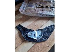

Lightening the seat
Bad News:
Waiting for 6m of 25mm tube to complete top rail layout of frame.
Spent £5 on branded batteries for welding helmet as generic batteries only seem to last a few days.
[Edited on 17/10/22 by Prof_Cook]
Hi, An ambitious project that should look great when complete.
I notice you are using an arc welder. I had the same intention 35 years ago and soldiered on.
Then a mate loaned me a mig to try out.
Why had I not discovered this machine earlier!!!
Used the mig ever since.Better welds and much easier. That mig has now built many chassis.
Maybe you could find a cheap mig on ebay, and then find your nearest Adams Gas agent. ( make sure you use a proper slug/ball flow meter, it will save
you a fortune over the round dial gauges.)
I just got a back payment on the pension, bought an R-Tec ac-dc 200amp Tig, so now to learn and do ali and SS welding.
Cheers Neville, many thanks for the comments. Yes a MIG would be good but given I am retired, my only unlimited resource is time, funds (as for all of
us) given the cost of living crisis are limited and I am trying to build the car for minimum funds.
For example, I was reading another car builders web page and found out his car was burnt out in last stages of build so I had started to
"budget" for a fire extinguisher for the garage. But luckily a house across the village had the below extinguisher sitting outside on the
pavement along with some other items and when I asked the homeowner about it he said "if you can use it then please take it as otherwise it would
go to the skip".
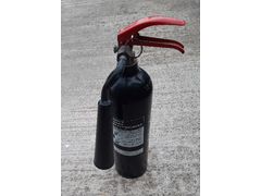

Extinguisher
Has cleaned up nicely, appears to be at charge weight and the lead seal on the pin is still wired in place.
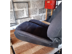
Stock seat was dismantled. Seat pan contoured section removed and replaced with some marine plywood left over from another project. Seat back
adjustment hinge spring removed, hinge drilled for lightness. Seat Pan drilled for lightness. Seat pad foam cut with hacksaw blade to reflect loss of
seat pan contour. and accommodate the thickness of the plywood sheet. Seat cover refixed to seat pan and back using plastic zip ties recovered from
roadside.
Seat now sits level on my workbench and the seat will sit a little lower (~20mm) in the final car and I will sit a little lower in the seat than
before, and even better there was no cost involved in this work:

SEAT
Modified seat weighs 11.3Kg including its 4 mounting bolts.
Seat covering will need to be replaced, but that (recovering) will be done after car is constructed and on the road.
[Edited on 26/10/22 by Prof_Cook]
So back in the garage finishing top rail lay up and then back to welding...
Car component expenditure is now = £285.80
Equipment expenditure = £348.24
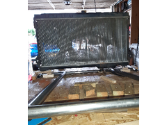
Back in garage for 1 hour today, just finishing top rail lay up for welding. Top rails being jigged upside down on bottom rail layout. Offered
radiator (upside down) onto top rails and there is clearance between radiator cap and top rails, and between hose connection points and cross rails.
Radiator will be offset in car and gap on right (left when rails are right way up) will be route for air intake plumbing. Photo shows view from front
cross member of top rails which is 4ins higher than longitudinal rails and thus become 4ins lower when turned right way up.

Test fitting radiator
[Edited on 15/11/22 by Prof_Cook]
Progress continues.......
Good News:
1. Welds continue to improve.
2. Top rails tack welded together.
3. Top rails "floated" over bottom rails using "skip" pallet wood lengths.
4. No more money spent.
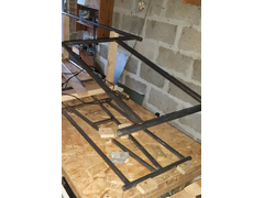

Floating Rails
Bad News:
1. Nothing project related, just the problem with the site over the weekend.
Next Steps.
1. As cant afford new radiator I am reusing the MX-5 radiator so now to test fit radiator and reduce length of the wooden "legs" holding up
the top rails until the radiator cant be fitted (cardboard tubing will be used to represent the forward suspension mounts uprights, then add 5mm onto
the "legs" and cut the tube uprights to that length and tack weld them into place.
2. Once uprights tack welded into place then start planning the layout of the triangulation pieces.
3. Other activity over winter will be for cold days to slim down the wiring loom...
[Edited on 29/11/22 by Prof_Cook]
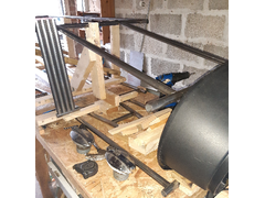
Carpentry again in December, setting up the jigs to hold the top rails exactly above the bottom rails and holding them in place ready for tack welding
the uprights. Sub-zero temperatures delayed work.

End of 2022
Steel for final uprights purchased and delivered this week. Steel tubes are being cut to length required and then fish-mouthed using a hand file.
"Pan-pipes" at left of picture are some completed. There will be 16 uprights between the top and bottom rails. Total cost of components for
the car is now £357.80
Kind person donated two lockable jaguar petrol caps (at bottom of picture), but will only need one.
Candidate nose cone sourced for free - very close to dimensions required, may be possible to adjust using hot air gun but that will be a future
experiment.
[Edited on 2/1/23 by Prof_Cook]
Top left stuff for components bin. Top right for Toolboxes. Rest of stuff for the local recycling bins.
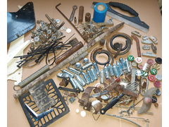

Finds Table
All found on road within 1.5 miles of my house.
Update and seeking information:
Good News:
More 1in 2mm thick wall tube received.
MIG Welder (flux cored) obtained and now put the "arc" welder to one side and started to practice welding with this "new" welder.
Trying different wire speeds and amp settings on pieces of off-cut, did a few good welds but on most attempts lots of spatter to so patience and
persistence needed to get used to this type of machine (could be earth clamp so stripping twin and earth mains cable to make large copper
"pads" to help with earthing) also will try a different roll of flux cored "wire", so will be a while till I get back to welding
frame components. I would be interested to hear of others experience with such welders or a pointer to any other forum/posts/sites detailing their
use?
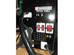

Flux cored MIG welder
Bad News:
Total spend on components for the car is now £398.80
[Edited on 20/1/23 by Prof_Cook]
Spent £14 on a new roll of branded quality flux cored mig wire - result - now welding with the "new" welder.
[Edited on 11/2/23 by Prof_Cook]
Being thinking for a while as to how to make bended pieces of steel to enable rounded bodywork to be "built" over the squarish frame...
Driving home recently noticed a semicicular piece of plastic lodged at the bottom of an embankment. Popped back when walking the dogs one afternoon
and turned out to be sizeable piece of roadkill debris in the left hand side photo below.
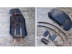

Free components
Once cleaned up and dismantled, ended up with 2 nice gently bent pieces of some 3mm thick steel (should be able to derust with angle grinder etc), and
two drilled plates which will be cut up for frame mounting brackets for various engine bay components.
[Edited on 16/2/23 by Prof_Cook]
Looks like a mudguard from a lorry
Progress as at end Feb 23.
Good news: Initial frame tack welded. 14 out of 16 uprights cut to length, hand fitted then tack welded. Measured and is square with tubes
perpendicular/parallel where applicable (Exception is tubes fore/aft of diff). 2 tubes remain
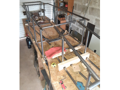

Initial frame
Bad news : Nothing really. Only reason last 2 uprights are still unfitted/welded is reviewing front layout design.
Plan for period up to Summer:
Fit last 2 uprights and then start the triangulation process. Will need to seam weld any hidden joints and then tack weld in the triangulation pieces
(ie on side frames, wishbone suspension location points and the top cross rail between engine bay and forward top rails).
Fit engine mounts.
Once frame is seam welded will be able to dismantle build table and transfer frame onto stands, lift engine/gearbox into frame and then fit/weld
triangulation in engine bay and start the straight and arched cross pieces which will carry the steering assembly (etc) and bodywork, and fit brackets
for engine bay components.
Fit differential and then the short PPF replacement to connect differential to gearbox. This will then determine the layout position for the seat (as
low as possible while clearing prop shaft/PPF).
Total expenditure to date is £760.
[Edited on 28/2/23 by Prof_Cook]
Before cutting steel tubes for the triangulation of the side rails, I wondered what options were available for the layout of the triangulation
tubes.
A chassis can be considered as a form of bridge between two load carrying points ( the front and rear axles) and I found this piece of simple analysis
of two types of truss bridge: https://digitalcommons.murraystate.edu/cgi/viewcontent.cgi?article=1164&context=postersatthecapitol
From this paper, option B below would seem to provide the lowest compressive forces on the tubes to the side of the cockpit and hence drivers postion.
So I will go with that layout.
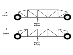

triangulation_options
[Edited on 8/3/23 by Prof_Cook]
First triangulation pieces cut to length and fitted to frame rails ready for tack welding. Off-cuts used for diff mounting rails. Magnets just for
show pending decision on diff mounting height relevant to bottom face of frame:
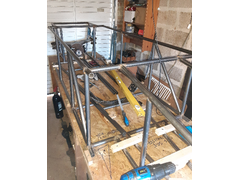

Triangulation_1
Total steel used to date is 31.5m (including 4 tubes still to be cut to length and installed). Calculated frame weight is 36Kg so will be interesting
to see what it weighs when removed from build table. Couple of metres of tube still to be obtained and welded on to support body work and form roll
hoop. So hoping to keep frame to about 45Kg.
[Edited on 15/3/23 by Prof_Cook]
Donor car developed 115BHP (I thought it was 105BHP) so to get to 307BHP/Tonne of the target car my project needs to max out at 375Kg. I have been
weighing some of my components so with some still to be finished and weighed my car will be some 75Kg over budget and thus power to weight should be
256BHP/Tonne..
Engine 124.7 = 27.74%
Wheels/Tyres 55.2 = 12.28%
Hubs/Uprights 48.8 = 10.85%
Frame 45.0 = 10.01%
Gearbox 36.3 = 8.07%
Differential 28.4 = 6.32%
Fuel Tank 20? = 4.45%
Wishbones 20? = 4.45%
Bodywork 20? = 4.42%
Seat 11.3 = 2.51%
Radiator 9 = 2.00%
Steering Rack 7.9 = 1.76%
Steering Wheel/Column 6 = 1.33%
ECU and Loom 5? = 1.11%
Lights 4? = 0.89%
Battery 3? = 0.67%
Handbrake 3? = 0.67%
Dashboard 2? = 0.44%
449.6
Challenge -74.6
[Edited on 15/3/23 by Prof_Cook]
Mind to make the passenger compartment stronger than the front or back unless you want to be sitting in the crumple zone.
Many thanks for the comment and Yes you are of course right and you have succintly articulated what I have been thinking of when thinking about the triangulation. Decided to have internal triangulation in passenger compartment but actual tube layout will be done once seat positioned and control layout fixed. Probably slanted "hoop" round from back of seat up to bottom of scuttle tied into top of frame rails.
quote:
Originally posted by Prof_Cook
Before cutting steel tubes for the triangulation of the side rails, I wondered what options were available for the layout of the triangulation tubes.
A chassis can be considered as a form of bridge between two load carrying points ( the front and rear axles) and I found this piece of simple analysis of two types of truss bridge: https://digitalcommons.murraystate.edu/cgi/viewcontent.cgi?article=1164&context=postersatthecapitol
From this paper, option B below would seem to provide the lowest compressive forces on the tubes to the side of the cockpit and hence drivers postion. So I will go with that layout.
triangulation_options
[Edited on 8/3/23 by Prof_Cook]
If you want a few good chassis papers to read you could go to
https://locost7.info/mirror/chassis.php
Final thesis A and B are good reads. As is the kitcaranalysis doc
Hi pigeondave many thanks for your comments and the links. Turning to your questions:
So what's the advantage of having a smaller compressive force in the members? - I assumed that having a lower compressive force in the cockpit
side members would reduce risk of collapse and thus improve the safety factor in this area.
Have you re-sized them as they are under less load? - No, kept to same size and wall thickness as the other frame members.
Which option gives the least deflection? - No knowledge.
My reading of the one page description of the experiment was that the max compression was identified for each truss design loaded at the three load
points and then the bottom design gave a max compression figure which was lower than. I also found the following "report" which chose Howe
design as having lowest stress: https://www.researchgate.net/publication/348579526_Designing_a_Truss_Bridge
I read the linked files and was intrigued in one of the papers at the description of a "ring beam" in the open top of the engine bay to
provide a degree of triangulation. I was looking at a "Y" brace from the rear of the engine bay/base of scuttle down to the front corners of
the engine bay with the "Y" brace being bolted into position (to allow engine removal/installation). So I will now be considering a
"ring beam" for the engine bay. That design choice will be made once the main frame is seam welded up and the engine/gearbox assembly loaded
into it so I can see exactly how much space is available between top frame rails and intake/exhaust manifolds.
[Edited on 20/3/23 by Prof_Cook]
Don't forget torsional stiffness of the chassis, or it will twist like mad in a corner.
While not the same type of car, and a different chassis style,
this might be an interesting read for you.
Unless you're working from a book design of chassis, you should really design the chassis last.
[Edited on 21/3/23 by coyoteboy]
coyoteboy many thanks for your comments and the linked analysis file. Yes I did previously read it and changed the design of the lower rails of the
frame to incorporate triangulation. As you correctly stated, torsional stiffness is a key element of handling and once the initial frame is seam
welded up and on stands, I will then mount the engine/gearbox and other major components to their mounting brackets and then see what opportunities
are available to incorporate transverse triangulation.
In an ideal world I would CAD the design and then spend months optimising the tube layout, but (1) I don't have the funds for that software and
(2) I have noticed on various forums that a proportion of projects fall by the wayside due to design inertia.
quote:
Originally posted by Prof_Cook
In an ideal world I would CAD the design and then spend months optimising the tube layout, but (1) I don't have the funds for that software and (2) I have noticed on various forums that a proportion of projects fall by the wayside due to design inertia.
£461 for components (steel tubes). final tubes for main frame purchased and delivered today. Now to cut, fit and tack weld them in.
£348 for books and tools.
No more money spent.
Work continues on cutting, filing and fitting tubes for tack welding.
Continue to find components (mostly plastic ties for the wiring loom) and some tools (a knife this month) when out walking the dogs:
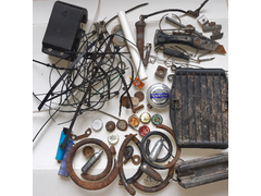

March_finds
A few pennies for the build kitty. The number of laughing gas cylinders is very few.
quote:
Originally posted by Prof_Cook
coyoteboy many thanks for your comments and the linked analysis file. Yes I did previously read it and changed the design of the lower rails of the frame to incorporate triangulation. As you correctly stated, torsional stiffness is a key element of handling and once the initial frame is seam welded up and on stands, I will then mount the engine/gearbox and other major components to their mounting brackets and then see what opportunities are available to incorporate transverse triangulation.
In an ideal world I would CAD the design and then spend months optimising the tube layout, but (1) I don't have the funds for that software and (2) I have noticed on various forums that a proportion of projects fall by the wayside due to design inertia.
Many thanks for the comments and agree as did 3 balsa models. Now using "full size" wood to confirm tube layouts. Been laid up this month,
but when back up and around I found a nice clean unstained/unpainted "HT = Heat Treated" pallet which has been broken up and is being used
for pizza oven fuel and for full frame modelling to confirm main tube layouts and confirm construction sequence.
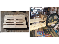

Pallet_Use
Now this has confirmed that will need to have steering column carried on bolted in cross members as steering column runs above rear of engine and to
allow engine to clear into the engine bay I will need to fit steering column and intermediate steering shaft above engine after engine
installation.
Weighed the battery today, 11Kg. A bit heavier than my original estimate of 3Kg! So my progress on the weight challenge is going the "wrong"
way. Cheapest option would be to dispense with electric start, fit small motorcycle battery and also save the starter weight and use rope starting as
there is now a "spare" pulley on the front of the crankshaft as I ditched the Power Steering and Air Conditioning:
https://www.youtube.com/watch?v=_0naTvrigBY&ab_channel=ShaketheFuture
Dont think "pull starting" would work on a MX-5 engine: https://www.youtube.com/watch?v=HyiQ_bHkDts&ab_channel=B%C3%B8mloBricks
Options to consider once the car is finished and on the road as suspect IVA examiner would be surprised at such novel ways of starting the car...
Other finds this month were an Encyclopaedia of F1 racing and Haynes manuals for Mini and BMW cars.
To create the above image of 2 photos alongside each other. The 2 original photos were sent by e-mail from my phone to my chromebook. Then opened
google docs, created a blank document, then inserted a table of 2 columns. Then inserted a photo into each cell. Took a screenshot and then opened the
screenshot, cropped it and then saved as a .jpg then uploaded to the site after reducing the scale using the rescale function.
[Edited on 23/4/23 by Prof_Cook]
There's nothing wrong with a handle to start it up...
Many thanks Mr Whippy for your comment. Yes I had thought about a starting handle as another option - appeals to me as pictures of the original
"target" car appear to show what could be an insertion point for a starter (handle or hand held electric motor?) in the air intake. Problem
is with my car is that the "stock" MX5 radiator being reused sits right in front of the engine and to get a starting handle onto the
crankshaft pulley would require me making a 25-30cm diameter hole in the lower middle of the radiator matrix - I don't think my fabrication
skills would be up to making such a hole in the radiator water tight!. Also I have no knowledge if the MX5 Mk1 engine could be started using a
starting handle...
Resigned to keeping current battery and starter motor until car mobile then will investigate the art of the possible.
[Edited on 25/4/23 by Prof_Cook]
Total expenditure to date, including latest steels and sundries delivered into workshop. Been out of workshop for last 6 weeks, but now back in. Next few weeks is for practicing arc welding on off-cuts to improve my welding before seam welding basic (triangulated) frame.
A few extras for the weight list, although I'm not sure whether they apply for you;
Propshaft/driveshafts.
Brakes discs/pads/calipers.
Pedal box (with cylinders).
Have you included the roll cage as part of the chassis? I bought mine very recently from 'the tube bender' on Ebay, I can recommend their
services if you want something you can trust should the worst happen. Again it's more weight though, I'd say my roll cage is about 15
kgs?
It's also interesting that you're reusing many of the parts. For example my car is a Seven base but with a Healey body on it, and I still
couldn't get the MX5 radiator to fit. You've got even less than me, so I'm impressed you've managed to get it to fit. I am reusing
one of the fans though.
Oh, and I will have to pinch your idea of cutting down a plastic barrel for wheel arches!! I have to put together some flared arches for my car
(slight failure in design), and I couldn't figure out how to do it. A plastic barrel makes a lot of sense.
Update:
Bad News : Progress not as fast as planned. Hand filing the ends of the triangulation tubes is taking longer than I thought it would!
Good News:
1. Frame construction continues.
2. No money spent since last update.
3. Sheet steel found at side of road will be converted into either firewall between engine and drivers compartment or perhaps cut up and used for
floor either side of transmission tunnel. The sheet steel was a "fire cowling":
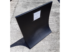

Free Sheet Steel
quote:
Originally posted by Slimy38
A few extras for the weight list, although I'm not sure whether they apply for you;
Propshaft/driveshafts.
Brakes discs/pads/calipers.
Pedal box (with cylinders).
Good news:
Triangulation side pieces finished and tack welded in. (Now cutting/shaping main cross triangulation pieces at front of engine and triangulation
pieces at rear/side of drivers position to ensure it is not the crumple zone).
Differential mounting position finalized - longitudinal carriers tack welded in and present the 2.2 degree tilt to the differential mounts which will
comprise of original differential mounts re-used. Vertical position should result in half-shafts being horizontal when car sitting on its wheels...
Bad News:
No real bad news (except for not getting enough time in the garage),
Total spend now £870 (more welding wire).
Diff bolts cut out of old sub-frame and jigged up to longitudinal carriers:
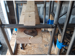

Diff bolts in jig
Adjustments made, double checked against diff drawings and draft rear wishbone dimensions. Diff bolts tack welded into position:
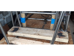

Diff bolts tack welded in
Wooden jigs got a bit hot. But stayed in place so now to put in triangulation to top/front tubes in the area. Alignment checked and differential
offered up and fitted well.
[Edited on 6-9-23 by Prof_Cook]
[Edited on 6-9-23 by Prof_Cook]
Differential bolts now hanging from vertical tubes to top rails and cross member tacked in which will become the rear top of the transmission
tunnel:
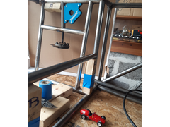

Diff Hangers
Piece of wood marked "A" used to ensure both vertical tubes are same spacing on both sides of the frame. Pieces of wood marked "B"
created by splitting one piece of wood to ensure both ends of the cross member are same height from bottom rail. Cross member alignment checked with
spirit level.
Still working on the project (haven't posted recently due to forum issues). Had to grind out and reweld the oldest welds as early welds just not good enough. Also delayed due to issues outside my control (including COVID-19). But now back in workshop with the welding mask on! (also got 2 strong workshop lights picked up from pavement outside someone who was moving house).
don't give up - just have a rest occasionally.