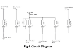
From left to right (if you cant read it) Indicator (L), main beam, ignition, oil, brake fluid, incicator (R).
David


Rescued attachment bright6 wiring.jpg

What do I have to fit between a LED and my wiring loom to have it work as a warning light? Only a resistor? And if so; what kind?!?
I like the Bright6 unit, but due to the shape of the rear, I can't fit it at the position where I want it, so I'm looking for an
alternative.....
Marcel
Here is the wiring diagram for the bright6 module, it will give you an idea of what you need. No values on resistors though.
From left to right (if you cant read it) Indicator (L), main beam, ignition, oil, brake fluid, incicator (R).
David


Rescued attachment bright6 wiring.jpg
It's many years since I did any electronics - but here goes.
R = V / I (resistance = voltage drop / current)
A notmal LED uses agout 20mA (0.02A)
The voltage drop accros the LED is fixed at about 1.2V
Battery voltage when engine running = 14V
Thus voltage drop required accross resisitor = 14 - 1.2 = 12.8V
using R = V / I above, R = 12.8 / 0.02 = 640 ohms.
Your LED may need a higher current (say 50 to 100 mA) thus requiring a lower value resistor.
I used the standard Maplins 10mm leds for my indicator warning lights, I joined the negative leads together and used a 470 ohm resistor, the other end
connects directly to the 12v signal.
Paul.
quote:
Originally posted by JonBowden
It's many years since I did any electronics - but here goes.
R = V / I (resistance = voltage drop / current)
A notmal LED uses agout 20mA (0.02A)
The voltage drop accros the LED is fixed at about 1.2V
Battery voltage when engine running = 14V
Thus voltage drop required accross resisitor = 14 - 1.2 = 12.8V
using R = V / I above, R = 12.8 / 0.02 = 640 ohms.
Your LED may need a higher current (say 50 to 100 mA) thus requiring a lower value resistor.
Different LEDs have different specifications. Find out what spec of the LEDs your going to use. Also experiance says that an LED similare spec to the example jon gives can work quite well with resistors ranging from 470 to 1000 ohms.
you can better search for an sheme that gives you always the same brightness.
It will add an component but its better quiality..
Soow if i was u also hookup an 7805 regulator
and start from there supplying the voltage to the leds...
if your battery voltage then drops to 12 volts instead 13 or 14
then nothing happens on the leds
regards,
TKS
quote:
Soow if i was u also hookup an 7805 regulator
Be aware that some of the extra bright LED's achieve the extra brightness by having two or more LED's in series. This means that the voltage
drop across the LED will be higher so make sure you get the spec for your LED's and run the numbers through the above formula.
If you want to achieve a stable brightness then you can use a different type of diode called a Zener diode along with another resistor to limit the
incoming voltage to something below 12V regardless of battery voltage. To do this you need to place the additional resistor between the incoming
signal and the existing resistor and then place the zener diode in reverse bias between the junction between the two resistors and earth.
A Zener diode in reverse bias (ie. Cathode to positive, anode to earth) will not conduct any electricity until the voltage across it exceeds the
defined threshold. The threshold voltage can be chosen when choosing the device. Once the threshold is exceeded, the zener will conduct quite easily
until the voltage falls back below the threshold when it will "switch off" again. You must have a resistor between the cathode of the zener
and the incoming signal to ensure that the zener doesn't conduct too much current as it tries to reduce the incoming 12V to, say, 5V. The
additional resistor will do this job quite happily instead.
So, what you will now see at the original circuit is a voltage of either 0V or the value of the zener diode, regardless of battery voltage and this
will ensure that the brightness of the LED's remains constant.
This circuit could be altered to allow brightness adjustment with the addition of a potentiometer. I can give some details if this is of interest.
Cheers,
Craig.
Cheers,
Craig.
Ok, so all in all it's not that complicated! Thanks, I'll give it a go.
Marcel
It is worth remembering that you can give the LED's a dual brightness by altering the resistor value according to the situation - useful for visibility with less dazzle during night / day modes.