Testing Fuel Gauge with Sender - Advice Wtd.
Dick Axtell - 28/6/18 at 04:40 PM
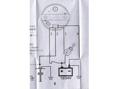
I have a new fuel gauge which I hope will match up with the recently obtained sender. Both are rated at 270 ohms/ 18 ohms. The wiring connections are
shown below.


Fuel_Gauge_Wiring
I plan to test gauge and sender off the vehicle, using this wiring set up. Should I also connect a resistance load in parallel with gauge and sender,
to prevent possible excessive current loading?
I welcome your constructive advice.
Smoking Frog - 28/6/18 at 05:01 PM
In my opinion no, there will be no current between sender and gauge, only a resistance value between sender and earth.
theconrodkid - 28/6/18 at 06:15 PM
some gauges run off 9 volts via a stabaliser, just to prevent the gauge going up n down with battery voltage, should be written on the units or in the
paperwork if you have any, worth a punt round on-line.
gremlin1234 - 28/6/18 at 07:33 PM
quote:
Originally posted by theconrodkid
some gauges run off 9 volts via a stabaliser, just to prevent the gauge going up n down with battery voltage, should be written on the units or in the
paperwork if you have any, worth a punt round on-line.
the old style gauges ran on a nominal 9 or 10V system. but that was a by-metallic
strip, switch open and closed. (quite slowly, but a early form of 'pulse width modulation' for voltage control.)
I would recommend a modern 9V (7809) or 10V regulator in the circuit
actually for testing, just use a pp3 9v battery
wylliezx9r - 29/6/18 at 07:05 AM
You should wire it up as per the diagram.
gremlin1234 - 29/6/18 at 02:04 PM
quote:
Originally posted by wylliezx9r
You should wire it up as per the diagram.
yea,
looking at it again, the gauge appears to have its own voltage regulation, in that it can be used 12/24V
Dick Axtell - 1/7/18 at 02:58 PM
quote:
Originally posted by gremlin1234
quote:
Originally posted by theconrodkid
some gauges run off 9 volts via a stabaliser, just to prevent the gauge going up n down with battery voltage, should be written on the units or in the
paperwork if you have any, worth a punt round on-line.
the old style gauges ran on a nominal 9 or 10V system. but that was a by-metallic
strip, switch open and closed. (quite slowly, but a early form of 'pulse width modulation' for voltage control.)
I would recommend a modern 9V (7809) or 10V regulator in the circuit
actually for testing, just use a pp3 9v battery
So - wired up gauge as per diagram above, and tested using PP3 batter, as suggested by gremln1234.
And it doesn't seem to work  ! The gauge definitely makes a noise, but there is no needle deflection.
gremlin1234 - 1/7/18 at 03:06 PM
ok, try it on a car battery
David Jenkins - 1/7/18 at 05:09 PM
quote:
Originally posted by gremlin1234
quote:
Originally posted by theconrodkid
some gauges run off 9 volts via a stabaliser, just to prevent the gauge going up n down with battery voltage, should be written on the units or in the
paperwork if you have any, worth a punt round on-line.
the old style gauges ran on a nominal 9 or 10V system. but that was a by-metallic
strip, switch open and closed. (quite slowly, but a early form of 'pulse width modulation' for voltage control.)
I would recommend a modern 9V (7809) or 10V regulator in the circuit
actually for testing, just use a pp3 9v battery
You'd be better off with one of these - they give a lot
of power, are tiny in size and give off hardly any heat.


 ! The gauge definitely makes a noise, but there is no needle deflection.