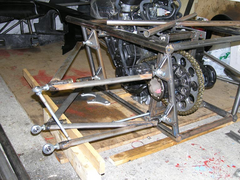
They are rather long but after seeing similar on some of the cars at goodwood, I think that they will be ok.
Triangulation plates will be welded in and possibly a small tube across the widest span.


Description
[img][/img]

Todays progress. Uprights are being plated at the moment so will be a couple more days before I can try them in place.
They are rather long but after seeing similar on some of the cars at goodwood, I think that they will be ok.
Triangulation plates will be welded in and possibly a small tube across the widest span.


Description
[img][/img]
I love seeing these updates for your car.
You are making some real progress.
Have you done any design work on those wishbones to see how they perform with regards to camber control? I notice they are fairly close in length. I
suppose the fact that they are quite long means less change in camber through their arc.
What uprights are you using?
That wishbone tube looks the part 
it also looks kind of awkward to join to the rod end tubes though, inserts for these would be nice, and probably difficult to make as well 
What kind of plating are the uprights getting?
Cheers
Alex
PS
Is this your day job or are you actually a millionaire just trying to fill up your day?

oval inserts would've been very tricky to make! I would've used round myself, and put the roses horizontal rather than vertical (ie, bolts
vertical rather then horizontal). This would've saved the kink at the front of the upper bone - its quite a change in angle and is compressed in
both acceleration and braking.
Amazing progress though. 
Are you mounting a starter motor to engage that gear on the same spindle as the bikes sprocket?
I've been looking at the reverse problems on a chain diff, have you more details if that's your intentions.
Out of interest, what sort of diff are you using? Are they readily available?
Cheers
Ken
Plenty of things to answer!
Firstly I am not a millionaire! I am a self employed electrician who works shifts. This gives me some unusual hours but also means I have chunks of
time that most people don't.
The diff can be any sierra diff stripped down as the ratio is not important. The sprocket size does all of your ratio setting.
Mine is an lsd from an XR4 X 4. I bought it from another locoster who got it from Zcars.
The starter motor reverse is relatively expensive as I bought it from Jon at Lynx AE racing. It cost me £270 + vat. It consists of a geared starter
(50% more torque for less current) a fixing plate plus a cog with an internal thread that replaces the drive sproket nut. I still have to make some
bushes up to space the reverse plate off the engine.
The reason my wishbone rod ends are vertical is because of my suspension design. I am using airbag bilstein shocks that use a compressor to raise and
lower the car. This gives me ground clearance of 0-6" with normall ride height of 3".
If you check my photo archive, you will find some drawings showing camber gain and loss. My bones follow this layout exactly.
The bones are different lengths. The angle of the rear subframe mounting points are not very clear in the photo.
The long bones plus the variable ride height means that I do not want large camber gains etc or I will have bad tyre wear.
[Edited on 25/6/2007 by nitram38]
quote:
Originally posted by ecosse
That wishbone tube looks the part
it also looks kind of awkward to join to the rod end tubes though, inserts for these would be nice, and probably difficult to make as well
What kind of plating are the uprights getting?
Cheers
Alex
PS
Is this your day job or are you actually a millionaire just trying to fill up your day?

I like the mounting off the brackets to the frame.
Are you getting the rose joints for free? 
I presume that it's gonna be a low rider. As i'm looking at the lower wishbone mouting.
Great to see your progress, much better than mine 
I bought the rose joints from McGill Motorsports. They are low cost when compared to other suppliers.
The brackets were designed in solidworks from sheet and cnc'ed for me. They were tig welded.
The bottom of the chassis will run 3" from the road.
The ride height can go as high as 6" or rest on the ground.
The bones will not be horizontal but the bottom one will run slightly downwards towards the upright and the top bone will run slightly upwards.
The following drawings are slightly exagerated in the up and down position to show camber changes.
Description
up
[img][/img]