
Rear suspension idea
Alan B - 22/12/04 at 07:19 PM
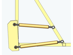
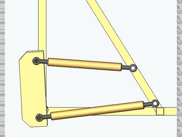
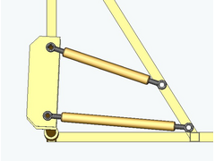
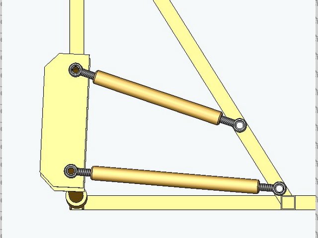
Comments?
I'm trying to develop something simple and easy to fabricate.
It's basically a trailing arm/upright and two lateral links.
[Edited on 22/12/04 by Alan B]

Sorry guys the pics aren't working....look in my archive under R Susp or similar
[Edited on 22/12/04 by Alan B]
sgraber - 22/12/04 at 08:01 PM
Sorry Alan, I searched your entire site and could not find a section named archive nor any photos of a new rear suspension design!
Can you point me there with a link?

Graber
Cita - 22/12/04 at 08:22 PM
I think Alan means the photo archive on here Steve.
sgraber - 22/12/04 at 08:34 PM
quote:
Originally posted by Cita
I think Alan means the photo archive on here Steve.
Argh. I misread to say Look at my website.... Will pay closer attention!
Alan B - 22/12/04 at 08:45 PM
quote:
Originally posted by Cita
I think Alan means the photo archive on here Steve.
Spot on...
I'm sure I inserted the image correctly...I have done lots of them....but it did not work...
Peteff - 22/12/04 at 08:48 PM
It looks like it will lock up as it stands there Alan or swing in an inwards arc. Any way of animating it?
sgraber - 22/12/04 at 08:54 PM
Yeh, I see it now.
To me it seems quite similar to the old VW swing arm suspension. From looking at it I think that you will experience a large amount of negative camber
under bump and positive camber in droop. Also this design may be susceptible to jacking the same as the Vdub suspension does.... Or am I missing
something here?
JonBowden - 22/12/04 at 08:58 PM
reminds me of what I believe is a lotus experimental version of the seven - I think it was refered to as the type 37
Rescued attachment l737ag9.jpg
Alan B - 22/12/04 at 09:00 PM
quote:
Originally posted by Peteff
It looks like it will lock up as it stands there Alan or swing in an inwards arc. Any way of animating it?
I'll look at animating it..I have already moved it within solidworks.......no it doesn't lock up...the main arm is rose-jointed as are the
two links...
JonBowden - 22/12/04 at 09:00 PM
another view
Rescued attachment l737ag4.jpg
Alan B - 22/12/04 at 09:01 PM
quote:
Originally posted by sgraber
Yeh, I see it now.
To me it seems quite similar to the old VW swing arm suspension. From looking at it I think that you will experience a large amount of negative camber
under bump and positive camber in droop. Also this design may be susceptible to jacking the same as the Vdub suspension does.... Or am I missing
something here?
Steve, it's unlike the VW stuff in that you have good comber control.....picture the two rear links acting like front wishbones.....
I'm going to work on the animation...
Aloupol - 22/12/04 at 10:21 PM
IMHO while it's quite different it gives nearly the same result as the BMW system, with angled rotation axis which give camber gain and anti
squat.
I don't understand how is the camber gain controlable, for me it's at a high value, and difficult to change.
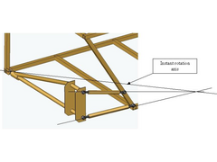
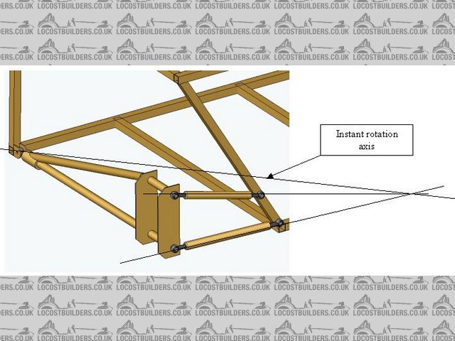
Rescued attachment 2RSusp2.jpg
Matthew_1 - 22/12/04 at 10:22 PM
With that design the suspension will pivot laterally on the front joint as it goes through bump and droop. It will effectively toe in and out quite
heavily - it would be interesting to see how much toe change there is in the model.
Having looked at the picture above you're going to get toe out on bump, which means on a bend the outside, heavily loaded wheel will go into toe
out, causing oversteer.
[Edited on 22/12/04 by Matthew_1]
Alan B - 22/12/04 at 10:28 PM
I mean camber is controllable by design as in a regular unequal length non-parallel two wishbone front system...(ala Locost).......or am I missing
something...?
Don't forget I'm looking for reasonable handling not neccessarily F-1 standards....
Yes there will be castor change (to give antisquat?)...and some small toe change...but I feel the camber should be fairly well controlled.....
Thanks for the input so far guys..
Ratman - 22/12/04 at 10:32 PM
I like this simplicity. I once sketched all sorts of rear suspension alternatives and comparing them on the basis of the number of rose-joints
involved, and what you have is about the simplest. The problems are:
1. The wheel does steer a bit with suspension movement. This need not be a bad thing if well controlled.
2. The links going forward have to accept quite a bit of bending load, so they have to be substantial (= heavy). The longer they are the better, and
this adds even more weight.
3. Brake anti-dive. If the brakes are on the hubs (other then inboard on the dif) then when the brakes are on, the suspension "retracts" so
you loose grip on the road. The wheel skips. This is the reason why bikes have an additional "parallel" link for the rear brakes. Again,
this effect is reduced if the link is a long one.
All in all, it is probably better to put a reversed wishbone in for one of the inward links, and have two trailing arms. Like the Lotus example above.
The upright is more complcated, but the chassis pick-up points are much the same.
Cheers, Brian
violentblue - 23/12/04 at 04:11 AM
RSUSP
Rorty - 23/12/04 at 05:58 AM
Alan, may I ask what your train of thought was/is for this design. As per usual, I arrive late and most of the points I can think of have been
mentioned. I don't think it's a complicated design, but it seems to present more problems than it solves. It would also be fiddely to set up
and with 5 rose joints it would be fairly expensive. Obviously, solid bushes are out of the question.
Would a semi trailing arm with a wishbone-like top link not be easier and cheaper? Maybe something already fills the rear corner hence the peripheral
design?
[Edited on 24/12/04 by Rorty]
Alan B - 23/12/04 at 12:44 PM
Rorty...you have hit the nail on the head spotting my other motive...space.
From working on my current design using transverse FWD style power trains you find that locatations for conventional wishbones are very limited or you
are forced into very short wishbones.
I feel the current rear suspension I have on the Meerkat, while workable is quite complex....I'm just really throwing ideas out there for
feedback....
Steve, do you agree on the lack of space for wishbones comment?
Alan B - 23/12/04 at 01:22 PM
Well.....I'm feeling a bit happier....my idea is basically the same as the Lotus Esprit......never known for terrible handling if I recall....
It has a long trailing arm with hub built in and two lateral links (the driveshaft is one of the links)

Alan B - 23/12/04 at 01:28 PM
quote:
Originally posted by Rorty
........ Obviously, bushes are out of the question........
Not neccessarily....if I can keep my links farly long, my suspension travel farily short and my bushes fairly soft it could be doable....
My model shows minimal side movements when travel is minimised and links maximised.
Sorry guys if it sounds like I'm arguing back at everything...I'm just trying to respond to everyone's comments and observations.
Again, thanks and keep it coming...
sgraber - 23/12/04 at 03:49 PM
I completely agree about the lack of space. A fact that drove me somewhat towards the use of deDion for my first build.
I still think that there will be lots of camber change over your range of travel. I mean, the lateral link pivots on a single point and the hub is
perpendicular to this lateral link. When the link pivots, the wheel will camber in and out. Just like the old VW suspension. Ever seen a lowered VW?
The rear wheels have incredible camber! Because of the single pivot.
The trailing arms transfer the driven load back into the chassis and control the castor. They flex in camber, so camber is directly correlated to the
length of the lateral link and the amount of travel.
Please smack me if I'm being thick, but I have animated this in my mind and can't see it any other way...
Alan B - 23/12/04 at 04:06 PM
Steve, try to imagine the two lateral links being equal and parallel...then there would be zero camber change....the camber control is purely a
function of their length and parallelism...(just like a locost front end)....the trailing arm just follows the path the links lead it......dont forget
the big joint at the end of the trailing arm is compliant and not acting like a regular bearing.
Or am I missing something....?
Alan B - 23/12/04 at 04:22 PM
Ok...these are three rear views....
Someone tell me why camber control here is different to a locost front.....I'm not talking about specific geometry...just the principle..
droop
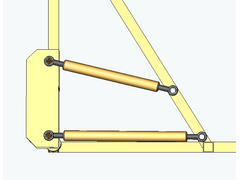
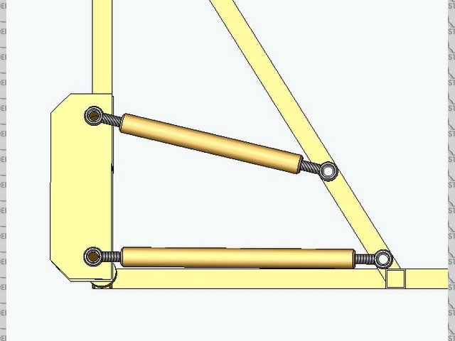
level
bump
kb58 - 23/12/04 at 04:50 PM
It is the same... The front link will just cause toe in/out during travel.
Alan B - 23/12/04 at 05:01 PM
quote:
Originally posted by kb58
It is the same... The front link will just cause toe in/out during travel.
Agreed....but it is not much with a long link and short travel.
How much toe change constitutes a significant problem?
Any opinions?
sgraber - 23/12/04 at 05:21 PM
Well I just confirmed my suspicions. I am totally stupid and not worthy to participate in this conversation! LOL  (really!) I had your design turned
sideways with the single triangulated link being the lateral and the dual links facing forwards. And I couldn't figure out why you wanted so much
anti-squat!!!!
(really!) I had your design turned
sideways with the single triangulated link being the lateral and the dual links facing forwards. And I couldn't figure out why you wanted so much
anti-squat!!!! 
As soon as you mentioned Locost front, it all came into focus...
I'll get my coat.
Graber
PS- It's not THAT different than what you already have built...
[Edited on 12/23/04 by sgraber]
Alan B - 23/12/04 at 06:09 PM
quote:
Originally posted by sgraber
PS- It's not THAT different than what you already have built...
Exactly, so it won't need much in the way of frame mods....but it will allow me to get rid of the Toyota hub and fabricate a hub/trailing arm in
one piece...using the one piece hub assemblies that are just a bolt on job....and save a bunch of links and rod ends.
I just measured the toe change...from level to around 3" bump its about 0.015"...less than 0.5mm
It will need engineering for the optimum geometry, but I think it's a go.
tadltd - 23/12/04 at 06:21 PM
Alan,
Which way does the toe 'change' in bump?
From what I can picture (and I may be as wrong as Mr. Graber here - but then I would be in good company!) this set-up will give toe-out in
acceleration, and toe-in during braking, which I believe is what you want...
...to a certain degree.
Also, are you running without ARB's? Is this why you have so much camber control?
Alan B - 23/12/04 at 06:28 PM
Steve, as drawn so far the it toes in by around 0.06 degrees.....
The positions of the links and chassis pick ups are a pure guess as shown so far....the goemetry is probably miles out as is now.
I have given no though to ARBs at this stage.
Aloupol - 23/12/04 at 06:32 PM
quote:
Originally posted by sgraber
I had your design turned sideways with the single triangulated link being the lateral and the dual links facing forwards.
I did exactly the same confusion, so there's more than one stupid.
Now put in the right side I understand, it seems OK..
There is still a lot of anti squat since the motor (or braking) torque tends to turn the trailing arm and to extend (or compress) the spring when
accelerating (or braking) but it's not a problem, a lot of cars have good behaviour with simple trailing arms.
Another issue could be the bending of the trailing arm under cornering force. The Lotus member seems huge, probably for that reason...
[Edited on 23/12/04 by Aloupol]
kb58 - 23/12/04 at 10:07 PM
quote:
Originally posted by tadltd
... this set-up will give toe-out in acceleration, and toe-in during braking, which I believe is what you want...
...to a certain degree.
I though the holy grail was slight toe-in whenever the suspension moves away from its rest position. AFAIK you never want toe out. Toe-out under
braking would make the rear end squirrely (sp?) OTOH I agree it's all by degree, that a "little" toe is okay, whatever that means...
I'll sit down now.
kb58 - 23/12/04 at 10:10 PM
quote:
Originally posted by Aloupol
Another issue could be the bending of the trailing arm under cornering force. The Lotus member seems huge, probably for that reason...
[Edited on 23/12/04 by Aloupol]
I don't think it's possible to bend the trailing links. There's a pivot at one end, and the other end is free to move up and down (the
axle) The only way it can bend is if one end tries to move and the other end is fixed.... neither are.
Aloupol - 23/12/04 at 10:23 PM
... Or if there's an important torque or load (there are both actually) between the supported nodes.
tadltd - 24/12/04 at 02:00 AM
Usually, when cars with unequal length wishbones are set-up, there is slight toe-in on the rear which is compensated for during acceleration, when the
wheels want to toe-out (i.e. they'll tend towards being parallel to each other rather than have an obvious toe-out condition).
On the front it's usually the opposite (slight toe-out) for the opposite situation, i.e. it tends towards toe-in under braking for stability.
Which is a good thing on the rear, too!
But then this is for a conventional unequal length double wishbone arrangement, which is not what Alan has... :s But it seems like that arrangement
will give the correct suspension 'behaviour' for stability.
Anyway, that's enough for this side of Christmas - have a good one, everyone! Hope Santa's good to you!!
locost_bryan - 24/12/04 at 03:27 AM
Alan,
I keep thinking of the "traditional" arrangment single-seaters had in the seventies - upper and lower lateral links (like yours) and twin
semi-trailing radius arms, effectively giving 2 very wide-based wishbones.
I presume you space limitations would prohibit that design (and it's requirement for 8 joints per side!
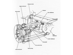
Your design seems similar to the Nissan 300Z IIRC
Ratman - 24/12/04 at 07:50 PM
Hi Bryan.. I think it is classically 9 or 10 joints per side. You need at least one more to stop it steering. It certainly is a lot of joints. Brian
(in Wellywood)
JoelP - 24/12/04 at 08:39 PM
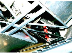
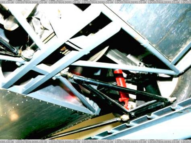
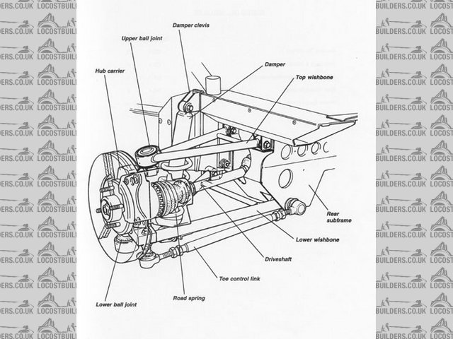
hey guys. this set up is very similar to a set up posted recently - IIRC, it was in an archive down a link i had followed from a new builder. The only
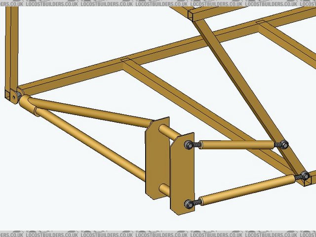
difference was that the lower bone had two joints at the hub end, to prevent steering. This is much like the underneath view photo posted further up
the thread.
in the scheme proposed by alan, i think that it would be hard to keep the wheel facing forward - what actually would stop it steering?
when i saw the photo before (maybe 3 weeks ago, before i got cut off... ) i was impressed and remembered it. I also posted in the thread a few
comments about it. I will try to dig it out, if my memory serves well!
) i was impressed and remembered it. I also posted in the thread a few
comments about it. I will try to dig it out, if my memory serves well!
[Edited on 24/12/04 by JoelP]
JoelP - 24/12/04 at 08:43 PM
here we go...

this is from 7/12/04, on the locost gt40 thread. ross is the chaps name, you can work out his website from the link above!
JoelP - 24/12/04 at 08:45 PM
note that the bit that goes forward (technical term) is split in two, to avoid the hub pivoting forward (maybe the cause of the earlier comments about
the setup locking up?)
Alan B - 24/12/04 at 09:48 PM
quote:
Originally posted by JoelP
- what actually would stop it steering?
The fact that the trailing arm and hub carrier are one solid piece....
JoelP - 24/12/04 at 10:47 PM
there is that, i suppose...
cymtriks - 16/1/05 at 09:14 PM
toe out is supposed to be a no-no on a rear middy suspension. BMW get around this by having a squashy front bush and hard lateral link bushes so that
twhen a side load is present the front of the trailing arm toes in thus undoing the links natural geometry. Lotus get around the problem by having
very long trailing links which minimise the problem.
How about sneeking a look under the Elise? The Elise has double wishbones of a conventional layout and they manage to get them round a transverse
engine.
JC - 23/1/05 at 10:29 AM
How about this? (Lotus Elise rear suspension).
Thought: The 'classic' Mini front suspension strongly resembles Alans design, except with a tie bar instead of trailing link and I remember
few complaints about the Mini's handling!
[Edited on 23/1/05 by JC]
Rescued attachment rearsuspension.jpg
bpaar - 27/11/05 at 03:01 AM
Can someone explain to me how there is toe in in this design?
From what I see, there is toe out with both rebound and compression (assumming the bottom control arm is level at rest). Any movement will shorten
the bottom control link giving toe out, the top link will twist the assembly and control camber. The amount of change is neglible with long arms, I am
just trying to understand the motion. What am I missing?
Bill
Stephant - 30/11/05 at 06:53 PM
Hi
I guess in rear view the wishbone and the
balljoints are at one hight,so no toe changes at moving.The effect may be,that the toe link is stiff (balljoints ) and the wishbone has rubber
bushes.At cornering the wishbone get's "shortened" through the bushes and the toe link doesn't.Toe in is the result,depending on
loads.
Best regards,Stephan
u401768 - 1/12/05 at 12:03 PM
OK - to throw a bit more in to the pot - Why not use two wide based trailing links, and ditch the lateral link - ie GTM Libra method - is easy to
package, puts the loads in to the tub, and means you can get the spring/coil over damper to lead straigh in to the tub too.
Alan B - 1/12/05 at 02:12 PM
quote:
Originally posted by u401768
OK - to throw a bit more in to the pot - Why not use two wide based trailing links, and ditch the lateral link - ie GTM Libra method - is easy to
package, puts the loads in to the tub, and means you can get the spring/coil over damper to lead straigh in to the tub too.
How does that handle camber?...Surely there is no camber change with that set up?
iank - 1/12/05 at 02:38 PM
quote:
Originally posted by Alan B
How does that handle camber?...Surely there is no camber change with that set up?
No there isn't, though camber can be set statically.
Works well on the mini and GTM , and the onyx firefox/clubsport use them and are reputed to handle well.
u401768 - 1/12/05 at 04:14 PM
Plus has excelent load transfer cherecteristics too - but the down sid is there is no camber change, but this should'nt be too much off an issue.
Stephant - 1/12/05 at 05:34 PM
Hi
low wight transfer means low roll centre too.With tailing arm suspension it is exactly at the ground,which is ok with a 7 type car.A full bodied car
with screens etc. should have it slightly higher.For getting Camber changes ,the swing axle of the upper upper tailing arm could have a different
angle.
Stephan
cymtriks - 4/12/05 at 08:25 AM
quote:
Originally posted by iank
quote:
Originally posted by Alan B
How does that handle camber?...Surely there is no camber change with that set up?
No there isn't, though camber can be set statically.
Works well on the mini and GTM , and the onyx firefox/clubsport use them and are reputed to handle well.
The axis of the upper wishbone slopes slightly down towards the centre of the car.
The result is that the top hub pivot moves at a small angle to the vertical, feeding in a completely linear camber change as the suspension moves.
This kind of suspension is also found on the Renault Spider, which also had a transverse engine mounted in the middle.
andkilde - 5/12/05 at 03:12 PM
Alan, how about a proper trailing arm?
Z-Cars use them on their Mini conversions (though I can't seem to find a photo at the moment). There were excellent photos in Race & Track
Cars a few months back where they featured the Mini and Bond Bug BECs.
Look like a fabricated version of a Mini rear trailing arm with a Sierra style C/V bunged-in in place of the stub axle.
Doesn't provide any camber control, but toe is perfect throughout suspension travel, roll centre is at ground level. No inner links at all. Could
use bushes throughout.
Cheers, Ted
Alan B - 6/12/05 at 02:26 PM
Good ideas guys....even more to think about...


