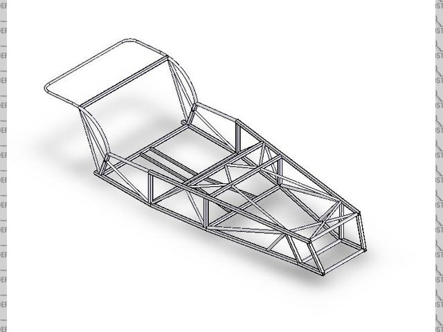

Rescued attachment dframe 140907.jpg

By a person who used to work for Lotus Engineering. Looks interesting.


Rescued attachment dframe 140907.jpg
Nothing new there though - it's basicaly a Caterham chassis!...........I've just done an almost identical 3D model after trawling the
internet for pictures of bare caterham chassis 
Yeah nothing new but it looks pretty tasty ... or will be when its complete!
Might be a dumb question but where does the rear suspension fit? Take it there is the back end to do yet?
it is not finished is it?
what about transmission tunnel? Itsn't it going to be quite flexible round there not to mention a cage to prevent the prop whicking your legs to
a pulp sould a UJ let go?
Work in progress. Rear, trans tunnel tubes, brackets, bracing, etc. to be put in. Lots more work to complete.
BTW does anyone have access to a late model Caterham spaceframe chassis? Need some dimensions for the 'rear bulkhead' A (width) and B
(height) measured from inside the rectangle. From pictures on the net I presume its 3/4" square section. Thanks!
[Edited on 25/9/07 by scudracer]
Latest update ...


Rescued attachment roadster assy 300907.jpg
More parts added (rear and front).  Still need dimensions for 'rear bulkhead' and tunnel. Can anyone shed some light? TQ.


Rescued attachment roadsterassy021007.jpg
call got all the dimms you need
[Edited on 2-10-07 by mangogrooveworkshop]
We are basing the centre tunnel dimensions on the Ron Champion book. Need a little more research on the front.
[img][/img]
Thanks. Exactly the tubes I've wanted to do in the engine bay but not sure of the dimensions. I believe the upper / of the two Y sections is
made of 1/2" square tube (16ga?) and the straight lower part of the Y is 3/4" round tube.
[Edited on 12/10/07 by scudracer]
You are correct, however the upper V's are only 1/2" because (On a Caterham) they meet 1/2" framing for the flooring support and
transmission tunnel, in your drawing I see you have a larger ( 1" ) square tube running across the chassis at the footbox, if you decide to keep
this than there is no reason not to use slightly larger than 1/2" tubing.
T
[Edited on 12/10/07 by Tralfaz]
Thanks Trafalz. The 1" going across needs to be modified, the centre should have a curve (to clear gearbox ...). 3/4" for the /? Hmmm ....
I'm a little confused here! Are you trying to build an authentic looking Lotus 7 series 3/ early Caterham 7 (because that's what
you're actualy drawing, and err very slowly it has to be said  ) or do you have other more cunning plans?
No confusion here Dave. 
He's obviously trying to put two tubes in as many places where a single tube will do the job, whilst leaving a couple of untriangulated bits,
just to keep us all guessing! 
Cheers,
Syd. 
The guy drawing (yes, very ... slowly) it wants it to look externally like the S2 drawing he found on the net (G. Cushing site?). That's why the
aim is not to do anything radically different. No cunning plans, nothing spectacularly different.
Powertrain - Ford Kent Crossflow 1600cc. Front uprights/brakes - Standard/Triumph/Caterham.
Syd when you say two tubes where one will do, do you mean the tube from the top of the rear top coilover mount to the lower side tube (seating
area)?
[Edited on 14/10/07 by scudracer]
Who Knows where Syd means, and if the past is any indication he seemingly takes pleasure in being vague . 
If that is the area he is referring to.... Isn't it an attempt to support the Trailing Arm mount?
[Edited on 15/10/07 by Tralfaz]
I think Syd is referring the the area ahead of the rear wheels marked with a red lines forming an X...one of the members would be redundant...you only need one diagonal to fully triangulate a quadrilateral shaped opening.......
Perhaps. Though I drew the Red lines,not him.
FWIW this is what Caterham does, rather than Triangulating with a single 1" diagonal they chose to use two 1/2" tubes forming the
"x" to increase hip width, and later to allow for a 1/2" Aluminum Honeycomb side panel to be fit and still flush out with the interior
of the frame.
T
They did but only on the later de dion chassis and they don't any more  ... not on the CSR at least. Looking at it though I'm not sure
what the section of the tube is on the CSR - it's a thin rectangular section rather than box by the look of it
You are right, they don't use it on the new CSR chassis, and to be honest I don't know if any changes have been made recently to the
'Classic' ,'Roadsport',etc....
T
Do you think the 'X' shape was more for side impact protection than stiffening?
Just had another look at your friends drawing..... quite where/how is he planning to mount the trailing arm(s) just out of interest.......? 
Does anyone has the original (not converted to .igs or something) solidworks file of this chassis?
Why "Y"'s for the engine mounting tubes, when straight pieces are the norm.
In the time this drawing had taken, I think I was in the process of starting my bodywork - scratchbuilt chassis, and bodywork.
Tell him to throw away his computer and start building
ATB
Simon
It's how Caterham do/did them and that's the point of the exercise I believe......although I'm not sure there's actually a
practical exercise going on here 
IIRC The Y's were created to give clearance for the bell housing, as the Caterham is 4 inches narrower than a Locost frame.
[Edited on 5/11/07 by Tralfaz]
4" narrower than standard book chassis??? Mines 4" wider than book. God, it'd be tight in a Caterham
ATB
Simon
- Frame drawing almost complete
- Ford product manager is donating his fathers '79 Escort Ghia 1.6-litre
- FRP wings to be completed by next week
Here's how it looks as of yesterday. Need to add in dash hoop, suspension brackets. Otherwise ... I think we can start cutting metal now.


The next step of to analyse it with FEA software, right?
Next step is to add in suspension brackets, tabs for dzus fasteners, gussets, etc. Would be good to have FEA done but not sure if 'Mr.
Lotus' who's drawing the frame in SolidWorks 3D has access to CosmosWorks.
[Edited on 9/12/07 by scudracer]
Have been thinking about chassis reinforcement. A good bulletin to read would be "Lotus Seven Chassis Reinforcement" issued by DSK Cars, Dec
13, 1978. It's posted on Simplesevens.org I believe. Also, I've been reading "The Racing Motorcycle" by John Bradley. There is a
nice picture of a subframe there by SDW Light Fabrications.
 Link to their website can be found below.
Apparently the subframe tubing is a mix of 16, 18 and 20 swg material, with the gussets being 20 swg. These are better than the thick plate gussets
illustrated in "Sports Car Chassis Design" by Mike Costin/Phipps because stiffness increases gradually (according to John Bradley's
book). The ends and corner of the gusset are left unwelded. The work continues
...http://www.sdwlightfabrications.co.uk/
quote:
These are better than the thick plate gussets illustrated in "Sports Car Chassis Design" by Mike Costin/Phipps because stiffness increases gradually (according to John Bradley's book). The ends and corner of the gusset are left unwelded.
Joe - yes I think so. The use of gussets will make the chassis stiff but the thing is they've got to be in the right place. No CosmosWorks so no
FEA. Guess we'll have to do it old school style? 