MakeEverything
|
| posted on 13/3/10 at 11:33 AM |

|
|
Supercharger inlet manifold
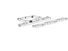
Ive been playing with the inlet manifold for the new engine;
 
Supercharged Inlet Manifold 1
The question i have, is that the supercharger must sit 50mm above the inlets to clear the fuel rail and injectors etc.
Other than welding 50mm pipes northwards to another plate, i wanted to open this to the forum to try and get an "Outside the box"
solution.
I eagerly await the response from the oracle of all knowledge that is LCB! 
Kindest Regards,
Richard.
...You can make it foolProof, but youll never make it Idiot Proof!...
|
|
|
|
|
tegwin
|
| posted on 13/3/10 at 11:35 AM |

|
|
Create a lowercase n shaped fabricated plenum joining thw two flanges together.... then sit the flange on top of the n...
[Edited on 13/3/10 by tegwin]
------------------------------------------------------------------------------------------------------------------------
Would the last person who leaves the country please switch off the lights and close the door!
www.verticalhorizonsmedia.tv
|
|
|
MakeEverything
|
| posted on 13/3/10 at 11:36 AM |

|
|
quote:
Originally posted by tegwin
Create a lowercase n shaped fabricated plenum joining thw two flanges together.... then sit the flange on top of the n...
[Edited on 13/3/10 by tegwin]
Good idea,but a bitch to make.
Kindest Regards,
Richard.
...You can make it foolProof, but youll never make it Idiot Proof!...
|
|
|
SPYDER
|
| posted on 13/3/10 at 01:14 PM |

|
|
Could you move the injectors?
I would then fabricate ( or probably machine from billet, knowing me) a large plenum box to fit betwixt charger and flanges. It would incorporate
short trumpets.
The injectors would go in the top face of the plenum and fire downwards directly into the trumpets.
If the charger could be slightly higher still it could include a small chargecooler inside!
It would definately have fins machined on its outer surfaces and have cold air blowing over it.
Maybe thats too much thinking "inside" the box!!??
Geoff
|
|
|
turbodisplay
|
| posted on 13/3/10 at 01:17 PM |

|
|
get 50mm thick ali watercut to make the spacer?
Darren
|
NOTE:This user is registered as a LocostBuilders trader and may offer commercial services to other users
|
MakeEverything
|
| posted on 13/3/10 at 01:39 PM |

|
|
quote:
Originally posted by SPYDER
Could you move the injectors?
I would then fabricate ( or probably machine from billet, knowing me) a large plenum box to fit betwixt charger and flanges. It would incorporate
short trumpets.
The injectors would go in the top face of the plenum and fire downwards directly into the trumpets.
If the charger could be slightly higher still it could include a small chargecooler inside!
It would definately have fins machined on its outer surfaces and have cold air blowing over it.
Maybe thats too much thinking "inside" the box!!??
Geoff
I did think about getting 50mm flanges cut, but they would be quite expensive, unless i get them made in 10mm sections and bolt / bond them
together.
Billet is definitely more expensive still, and i was going to make a plenum chamber for the supercharger to sit on with some air baffles in side. My
concern would be that because the charger would be sitting over the front two cylinders, that they would either leak air through the valves or starve
the other cylinders of air at higher revs...?
Kindest Regards,
Richard.
...You can make it foolProof, but youll never make it Idiot Proof!...
|
|
|
SPYDER
|
| posted on 13/3/10 at 02:48 PM |

|
|
Hi richard.
I doubt that any cylinders would starve. Most standard four cylinder engines feed from one end of the plenum using a single throttle body. Only a few
have multiple throttle bodies and most of those feed from a plenum with one end open.
You could start with the largest diameter pipe that will fit in the "vee" and fit short pipes off that to each cylinder.
Why are your flanges horizontal and not at an angle to each other? Are you retaining part of the standard manifold?
If you made a completely new manifold would it allow a larger diameter plenum tube?
Geoff
[Edited on 13/3/10 by SPYDER]
|
|
|
MakeEverything
|
| posted on 13/3/10 at 03:09 PM |

|
|
quote:
Originally posted by SPYDER
Hi richard.
I doubt that any cylinders would starve. Most standard four cylinder engines feed from one end of the plenum using a single throttle body. Only a few
have multiple throttle bodies and most of those feed from a plenum with one end open.
You could start with the largest diameter pipe that will fit in the "vee" and fit short pipes off that to each cylinder.
Why are your flanges horizontal and not at an angle to each other? Are you retaining part of the standard manifold?
If you made a completely new manifold would it allow a larger diameter plenum tube?
Geoff
[Edited on 13/3/10 by SPYDER]
The inlet ports are integral to the cylinder heads.
Kindest Regards,
Richard.
...You can make it foolProof, but youll never make it Idiot Proof!...
|
|
|
prawnabie
|
| posted on 13/3/10 at 03:16 PM |

|
|
I think he is saying that on most v6 engine the inlet ports are in the "valley" and and not horizontal - dunno how it works on your engine
though.
|
|
|
MakeEverything
|
| posted on 13/3/10 at 05:05 PM |

|
|
quote:
Originally posted by prawnabie
I think he is saying that on most v6 engine the inlet ports are in the "valley" and and not horizontal - dunno how it works on your engine
though.
Sorry, the last post was probably a bit brief. Was eating a hot jacket potato at the time!!
The inlet ports on my engine are flat and horizontal, yet in the "Valley" or saddle of the block, hence the need for a 50mm lift.
The inlets are also intergral to the cylinder heads as faras i can see without taking them off.
Engine is a 24V BOB 2.9 Cosworth.
[Edited on 13-33-10 by MakeEverything]
Kindest Regards,
Richard.
...You can make it foolProof, but youll never make it Idiot Proof!...
|
|
|
BenB
|
| posted on 13/3/10 at 05:10 PM |

|
|
quote:
Originally posted by SPYDER
Could you move the injectors?
I would then fabricate ( or probably machine from billet, knowing me) a large plenum box to fit betwixt charger and flanges. It would incorporate
short trumpets.
The injectors would go in the top face of the plenum and fire downwards directly into the trumpets.
If the charger could be slightly higher still it could include a small chargecooler inside!
It would definately have fins machined on its outer surfaces and have cold air blowing over it.
Maybe thats too much thinking "inside" the box!!??
Geoff
that's what I was wondering. Have the injectors spraying straight into the trumpet..... Would end up being quite tall though...
|
|
|
MakeEverything
|
| posted on 13/3/10 at 05:29 PM |

|
|
quote:
Originally posted by BenB
quote:
Originally posted by SPYDER
Could you move the injectors?
I would then fabricate ( or probably machine from billet, knowing me) a large plenum box to fit betwixt charger and flanges. It would incorporate
short trumpets.
The injectors would go in the top face of the plenum and fire downwards directly into the trumpets.
If the charger could be slightly higher still it could include a small chargecooler inside!
It would definately have fins machined on its outer surfaces and have cold air blowing over it.
Maybe thats too much thinking "inside" the box!!??
Geoff
that's what I was wondering. Have the injectors spraying straight into the trumpet..... Would end up being quite tall though...
The injectors are very low at the moment, and its jsut clearance for the fuel rail and connectors that i need. The point of all of this is to have a
supercharger and air plenum sitting on top, so moving the injectors wont really be much benefit.
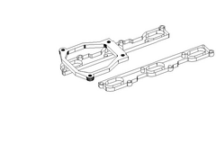
Maybe this makes the first look a bit clearer?
 
Supercharged inlet manifold 2
[Edited on 13-33-10 by MakeEverything]
Kindest Regards,
Richard.
...You can make it foolProof, but youll never make it Idiot Proof!...
|
|
|
boggle
|
| posted on 13/3/10 at 06:14 PM |

|
|
fabricate from tube and 4mm ali....
but best i dont do it for you as my efforts are crap....allegedley.........
just because you are a character, doesnt mean you have character....
for all your bespoke parts, ali welding, waterjet, laser, folding, turning, milling, composite work, spraying, anodising and cad drawing....
u2u me for details
|
PLEASE NOTE: This user is a trader who has not signed up for the LocostBuilders registration scheme. If this post is advertising a commercial product or service, please report it by clicking here.
|
MakeEverything
|
| posted on 13/3/10 at 07:08 PM |

|
|
quote:
Originally posted by boggle
fabricate from tube and 4mm ali....
but best i dont do it for you as my efforts are crap....allegedley.........
Since when??? All the stuff youve produced for me has been top quality and spot on the measurements.
Kindest Regards,
Richard.
...You can make it foolProof, but youll never make it Idiot Proof!...
|
|
|
MakeEverything
|
| posted on 13/3/10 at 07:54 PM |

|
|
 
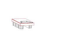
Supercharged Inlet Manifold 3
This is what ive come up with. a 50mm spacer, with the bottom part and sides welded in. Bolt the spacers to the manifold from inside, ten the
supercharger to the lid. Finally screw the lid to the rest of the plenum.
Kindest Regards,
Richard.
...You can make it foolProof, but youll never make it Idiot Proof!...
|
|
|
SPYDER
|
| posted on 13/3/10 at 07:58 PM |

|
|
Where are the injectors richard? Are they in the "vee", ie. under the charger or on the outsides of the manifold?
Is something like this absolutely not possible??
Geoff.
Excuse my poxy, ham-fisted pic !!
[img] [/img] [/img]
EDITED: Sorry richard, missed your previous post whilst creating my own.
I'm studying your pic now.
[Edited on 13/3/10 by SPYDER]
|
|
|
MakeEverything
|
| posted on 13/3/10 at 08:07 PM |

|
|
lookslike weve been drawing at the ssame time!!
Yes, exactly possible, but need the 50mm clearance under the plenum. The injectors are mounted there, as is the fuel rail, connectors etc.
Kindest Regards,
Richard.
...You can make it foolProof, but youll never make it Idiot Proof!...
|
|
|
SPYDER
|
| posted on 13/3/10 at 08:10 PM |

|
|
Hi Richard.
The red box part is going to need to be very strong to widthstand the mechanical stresses of mounting the charger on it and to avoid blowing up like a
balloon from manifold pressure. The lid will need lots of fasteners around the periphery and will need to be 5 or 6mm thick IMHO. If you could arrange
for an "O" ring seal that might be best but whatever seal it will need to be good to stand the occasional backfire.
Is it 50mm total or is the red box 50mm on it's own?
I would move the injectors to where the blue holes are on my pic and it becomes a simple box.
Geoff.
|
|
|
MikeRJ
|
| posted on 13/3/10 at 08:39 PM |

|
|
quote:
Originally posted by SPYDER
Hi Richard.
The red box part is going to need to be very strong to widthstand the mechanical stresses of mounting the charger on it and to avoid blowing up like a
balloon from manifold pressure.
I was thinking the same.
How about making a cylindrical (or maybe D shaped) plenum that runs down the middle with the ports connected via tubes with a suitable mandrel bend in
it? (Alfa V6 inlet manifold might yield some suitable tubes). Obviously the area where the supercharger flange is welded on will have to be flat.
[Edited on 13/3/10 by MikeRJ]
|
|
|
MakeEverything
|
| posted on 13/3/10 at 09:49 PM |

|
|
quote:
Originally posted by SPYDER
Hi Richard.
The red box part is going to need to be very strong to widthstand the mechanical stresses of mounting the charger on it and to avoid blowing up like a
balloon from manifold pressure. The lid will need lots of fasteners around the periphery and will need to be 5 or 6mm thick IMHO. If you could arrange
for an "O" ring seal that might be best but whatever seal it will need to be good to stand the occasional backfire.
Is it 50mm total or is the red box 50mm on it's own?
I would move the injectors to where the blue holes are on my pic and it becomes a simple box.
Geoff.
Hi Geoff,
Yes, the bottom plate and sides are to be 3mm with a 5 or 6mm top. It needs to be 50mm to the bottom plate, and the plenum in the drawing is 25mm at
the moment.
Kindest Regards,
Richard.
...You can make it foolProof, but youll never make it Idiot Proof!...
|
|
|


