spegru
|
| posted on 26/11/24 at 12:48 PM |

|
|
Thanks for that offer and for all the advice
Philip, regarding posting pictures, at the top of this page you will see a tab marked Photo Archive. If you go in there you can upload your photos
and once you have don that you can click on the uploaded photo and the system will supply a link that can be copied pasted into the forums.
You can have either a full size pic or an expandable one depending on the option chosen
Very clunky but it works
Anyway I have done that and I also found the ST200 manifold that I was getting confused by
Here are the two manifolds
ST220
 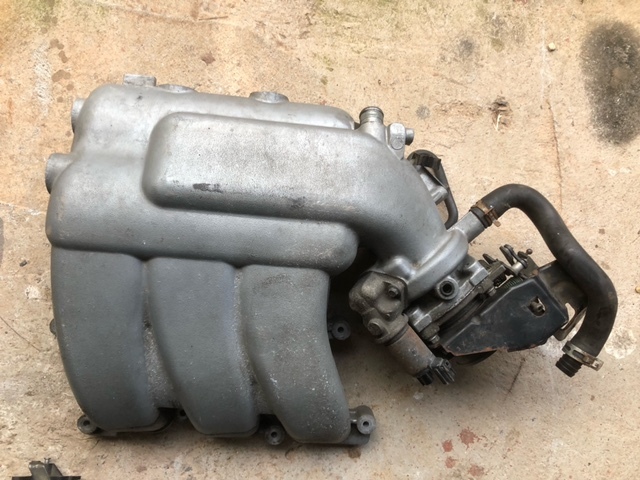
ST220 manifold
ST200
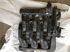 
ST200 manifold
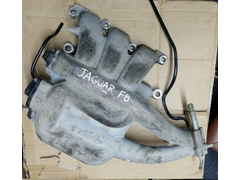
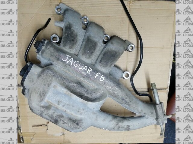
Unfortunately though mine is a different shape to either of these
Early AJ30 manifold
AJ30 manifold
The bulk of it is on the RH side of the engine vs LH for ST220 or both sides for the ST200. this means that I am going to have problems with all my
coolant plumbing
Meanwhile this morning I have been experimenting with the MEITE setup for the ME360 choosing various options but so far none has made any real
difference beyond the basic only running for a few seconds problem (after which it will restart and begin that same cycle again)
I am again suspecting my fuel delivery purely because of my very waggly fuel pressure guage . It doesnt do that when the guage is connected next to
the tank, only when connected next to the engine
See this vid (but ignore the part regarding the hiss from the manifold as that's now gone)
https://youtube.com/shorts/UO7k2sFVT8Y?si=rwEH4oUaC0Njyfu9
IIt may be that the pressure guage is just very poorly damped and is resonating in response to the injectors, but it does seem very odd. I did test
the flow rate by disconnecting the fuel line into a coffee jar. It filled the 2 litre jar in about 20seconds.....
Check out Invader Garage on Youtube
https://www.youtube.com/channel/UC3C55qk-tbKc0WjmxGqFoXg
|
|
|
|
|
spegru
|
| posted on 26/11/24 at 02:38 PM |
|
|
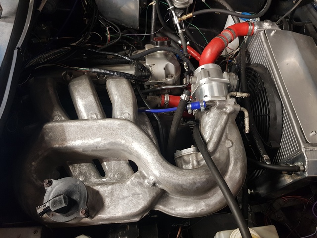
While I am at it here is the manifold from an XF 3 litre, which has pretty much the same engine (although I know its got differences around the
timing chain)
This also has its bulk to the right although there does seem to be more at the front than the original S Type AJ30
XF manifold
Check out Invader Garage on Youtube
https://www.youtube.com/channel/UC3C55qk-tbKc0WjmxGqFoXg
|
|
|
spegru
|
| posted on 26/11/24 at 05:14 PM |
|
|
latest video of my attempts here
https://youtu.be/2-I2feo-lw4
Check out Invader Garage on Youtube
https://www.youtube.com/channel/UC3C55qk-tbKc0WjmxGqFoXg
|
|
|
mgb281
|
| posted on 26/11/24 at 05:22 PM |
|
|
I spent this morning looking at my Jaguar engines (I have two of them and yes I know it's greedy) which was spurred by Steve's problems,
for those that don't know I am now getting closer to doing the paintwork, the engine has been in and out multiple times and three different
engine mounts have been fabricated. I initially thought that the ST200 manifold would work but it ended up too close to the bulkhead, heater and
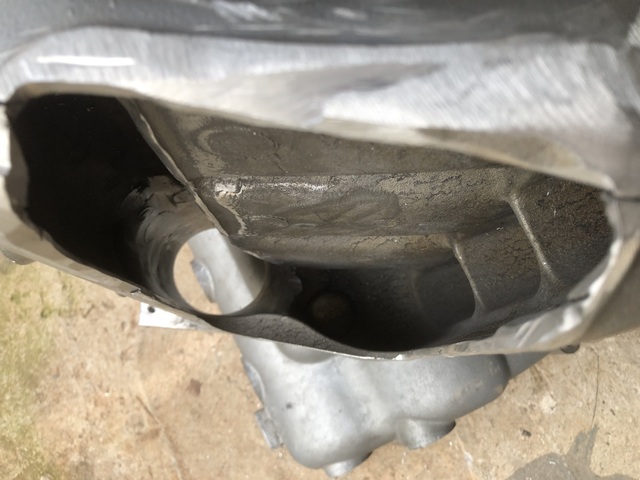
nearside bonnet hinge so I had a rethink and after buying an X type one I decided to carve up a ST220 inlet manifold. As you can see I sliced of the
inlet tract up to the plenum and removed the raised section for both access and bonnet clearance, the closed end was cut open and a 25mm block of
aluminium was welded in after drilling a 65mm hole in the centre. I used a burr cutter to blend the aluminium block into the interior of the
plenum.
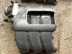 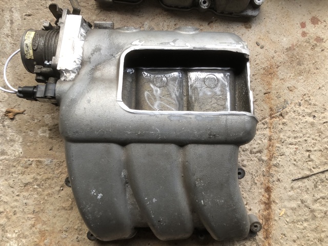
Modified ST220 inlet manifold
Modified ST220 manifold
Inlet manifold shelf
You can see that there is a shelf that runs the length of the plenum, the offside bank of cylinders is fed by the lower section and the nearside bank
by the upper section. The throttle butterfly works with one side of the flap feeding the upper shelf and the other side the lower. the shelf has been
shortened next to the throttle body by about 15mm to aid air flow. I will try and polish the upper surface of the shelf to improve airflow.
I had a good look at the engine with the S type manifold still and that open pipe feeds a small 3mm flexible hose about a metre long but I have no
idea where it went to. The rubber elbow on the PCV was good on both engines, however I think it would be easy to fabricate a rigid steel or copper one
|
|
|
spegru
|
| posted on 26/11/24 at 07:25 PM |
|
|
that all looks very impressive fab work. I'm trying to avoid very much of that although I did have to get an adaptor made for the Throttle
body.
I suppose the pipe you are referring to was my mystery hissing pipe near the lower IMT valve? It's now blocked off. There was a small tube in
that area that's no longer there. It went to the electronic fuel pressure sensor. Not sure why that was there but even my fuel pressure guage has
a release tube and valve for when you disconnect or reset, so I imagine could be something like that. But I'm not using that as Ive got a
mechanical pressure regulator with a vent tube back to the tank.
Ive also got that tube to the crank case that I hear gets cracked. Mine seems to be in good condition but as of now it's not connected to
anything else anyway.
[Edited on 26/11/24 by spegru]
Check out Invader Garage on Youtube
https://www.youtube.com/channel/UC3C55qk-tbKc0WjmxGqFoXg
|
|
|
spegru
|
| posted on 29/11/24 at 06:52 PM |
|
|
A bit of an update: It RUNS!
After fiddling around for ages worrying about fuel pressure, air bubbles in the fuel, fuel contamination I came across this page on the ME website
https://motorsport-electronics.co.uk/onlinehelp/html/4353.html
This led me to using the warmup table to enrich everything.
I know this is wrong but It WORKS!
Enough at least for me to be able to move on and cease worrying about fundamental issues
So in summary it seems the mixture was far too lean
Quite why that is and why MEITE did not tell me so, I do not know. A problem for another day week or even month
What a relief
Another vid is going up about this tonight
Check out Invader Garage on Youtube
https://www.youtube.com/channel/UC3C55qk-tbKc0WjmxGqFoXg
|
|
|
spegru
|
| posted on 8/12/24 at 09:40 AM |
|
|
Final update on this thread I think.
Eventually I got some proper feedback from ME including a new map that does not include my temporary fix using the warmup table.
It works!
I wish I knew exactly what they did to the map but this will do for now and I can be confident that there is no underlying problem
Check out Invader Garage on Youtube
https://www.youtube.com/channel/UC3C55qk-tbKc0WjmxGqFoXg
|
|
|
spegru
|
| posted on 16/12/24 at 01:56 PM |
|
|
or not final post on this thread,,,,,
Has anyone managed to get Cam Sync on the AJ30?
Ive tried every combo I can think of, and Ive used well shielded cabling - but nothing
I'm wondering if there is something different about the early AJ30 cam pattern?
thanks?
spegru.
PS and I'm still after info about the connectors on the cam/crank sensors & the 2 wire COP coils (they are all the same)
Check out Invader Garage on Youtube
https://www.youtube.com/channel/UC3C55qk-tbKc0WjmxGqFoXg
|
|
|
mgb281
|
| posted on 16/12/24 at 07:29 PM |
|
|
I can let you have 2 pin COP plugs at a later date, the Jaguar engine that I was hoping to buy is still with the seller. He has been trying to sell it
for eighteen months and cant be bothered to find a pallet!
I have no idea what you mean by cam synch but you must be getting an accurate cam signal to run the COPs or have I got that wrong? The up to 2002.5
engine has quite a few differences, up to the. The VVT was a simpleton/off switch but the later engine uses a continuously VVT. Other changes include
the inlet manifold and four pin COPS.
|
|
|
spegru
|
| posted on 4/1/25 at 04:28 PM |
|
|
Happy New Year everyone.
I am pleased to say that not only is the engine running, but that I have finally identified the correct connector type for the Coil on plugs, Cam
Sensor and Crank Sensor
They are 2 Pin Furukawa plugs,
They are listed as being for Ford Focus, Mondeo & Suzuki - but they are different from the COP plugs I previously found listed for Duratec.
There are a bunch of different plugs with a similar appearance but the distinctive aspect is the assymmetric oval shape, the yellow insert and the
pins being slightly offset downward
Here is the Ebay listing , where I got a set of 5, including the mating half that
I don't really need.
In fact this is a pretty neat waterproof plug set, currently at a very reasonable price of £8.34 for a complete set of 5 for the two pin version
required
Further investigation has revealed that these Furukawa plugs also exist in other versions with up to 16 pins
[Edited on 6/1/25 by spegru]
Check out Invader Garage on Youtube
https://www.youtube.com/channel/UC3C55qk-tbKc0WjmxGqFoXg
|
|
|
mgb281
|
| posted on 4/1/25 at 05:55 PM |
|
|
Good find Steve. Have you seen this Jaguar repair manual? If not its a useful one to add to your collection.
http://jagrepair.com/images/AutoRepairPhotos/Engine%20Repair%20Course%20Code%20168.pdf
|
|
|
spegru
|
| posted on 6/1/25 at 12:49 PM |
|
|
Thanks for that Philip. I hadn't seen it.
Now downloaded......
Check out Invader Garage on Youtube
https://www.youtube.com/channel/UC3C55qk-tbKc0WjmxGqFoXg
|
|
|
Partofthechaos
|
| posted on 9/2/25 at 12:23 PM |
|
|
Following on from your progress starting your engine, did you use both cam sensors or just one? I'm using an Emerald K6, I can only find one
place to assign a cam sensor, so I'm assuming one is fine?
I've asked Emerald about 17 times and not had a response. They can't manage to send me a base map either!
[Edited on 9/2/25 by Partofthechaos]
|
|
|
mgb281
|
| posted on 9/2/25 at 12:53 PM |
|
|
I am not sure if this helps but I bought an ex Rocketeer engine loom and it only had one cam sensor. Considering the ME442 could cope with two cam
sensors, VVT, Wideband O2 sensor etc it makes you wonder why they used such a cut down spec. I am going to add the extra sensors.
|
|
|
Partofthechaos
|
| posted on 9/2/25 at 12:55 PM |
|
|
Thank you, it does seem odd! Though it tallies with Emerald seeming to only have one place to assign a sensor, maybe one is enough. I have routed
both cables and this is my last bit of wiring to complete now. Keen to get it finished!
|
|
|
mgb281
|
| posted on 9/2/25 at 01:04 PM |
|
|
I am thinking that one is sufficient to run it but two enable the OE ECU to detect a fault if one cam is not varying properly.
|
|
|
Partofthechaos
|
| posted on 9/2/25 at 01:32 PM |
|
|
That makes sense, I hadn't considered VVT monitoring.
I'm planning to remove the shorter cable, so I can swap the remaining cable from one sensor to the other if needed. OK, forward we go!
|
|
|
spegru
|
| posted on 10/2/25 at 11:52 AM |
|
|
good to see the forum is working again
So far I have never been able to get cam sync with the ME360.
The Jaguar wiring is set up for two cam sensors although neither of those are screened so I replaced those sections with screened stuff a few weeks
ago.
but havnt pursued that so far as Ive other things to work on, but I really want that working.
Seems to me that in order for the cams to sync, the pattern needs to be recognised, which offers the possibility that either the wiring is reversed,
so reversing the pattern, or that since my engine is an early one with only 2 VVT positions, that the pattern is actually different from the one that
the MEITE software is expecting for a (later) AJ30 with continuous VVT - which would be a real nuisance as presumably it could need different firmware
for that pattern
Check out Invader Garage on Youtube
https://www.youtube.com/channel/UC3C55qk-tbKc0WjmxGqFoXg
|
|
|
mgb281
|
| posted on 10/2/25 at 12:51 PM |
|
|
Steve, would you like to have a look at my ex Rocketeer ECU, it was set up by ME so should be configured correctly. however if you read this;
https://www.pistonheads.com/gassing/topic.asp?h=0&f=47&t=1709711&i=760 you may beg to differ
|
|
|
spegru
|
| posted on 10/2/25 at 02:36 PM |
|
|
Thankyou Philip. Certainly I would. I also wonder whether you have / would be able to, upload the map that you have from the ECU, and simply email it?
It's not that big @1.2MB. Of course you'd have to power up the ECU to get it if you havn't though. Did I see that yours is an ME442?
I'm not sure whether that matters though as the map seems to all text as far as I can see. Of course I can also send you my (rather sketchy) one
too
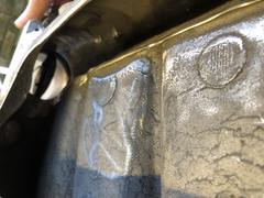
While I am here again, I thought it would be useful considering my concerns about Cam sync with regards to early/late AJ30s so I just popped over the
road to get a pic of my neighbour's 2017 Jag XF engine - just to illustrate the difference between the two versions
The first pic with the silver cam cover is mine, from a 1999 Stype - with only 2 VVT positions
 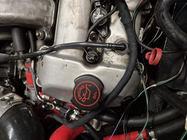
1999 AJ30
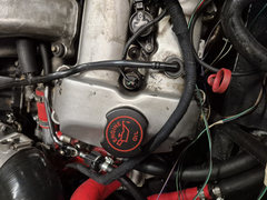
The second pic with he black cam cover is from the 2017 XF - with continuously variable VVT
 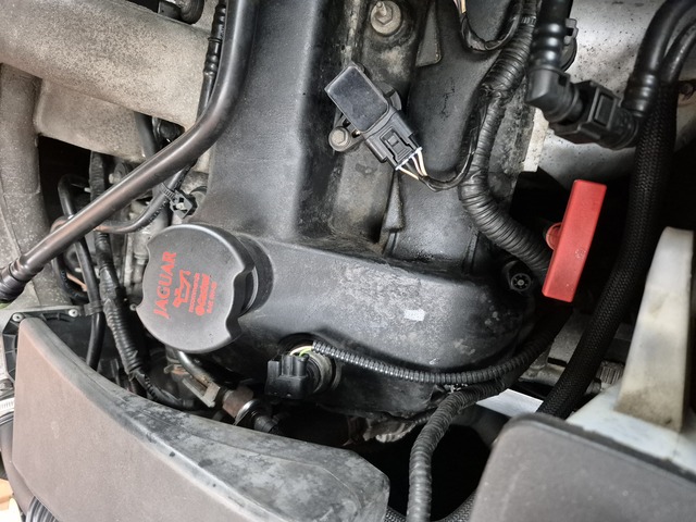
2017 AJ30
As you can see the cam control plug is behind the cam chain in the earlier and in front on the later one. Oil filler caps are also in slightly
different positions
And the question is do the cams both have the same sync pattern? and which on is built into the the Motorsport Electronics MEITE & ME360/442
Which version of the AJ30 have Forum members got?
Check out Invader Garage on Youtube
https://www.youtube.com/channel/UC3C55qk-tbKc0WjmxGqFoXg
|
|
|
spegru
|
| posted on 10/2/25 at 02:50 PM |
|
|
I also note that the MX5 shown on the Pistonheads/Rocketeer forum by 'Lewis's Friend', that you referenced, appears to be fitted with
the earlier type of AJ30.
This may be good news regarding my concern, but i am not 100% sure what ECU setup that car actually has (had - this was 2020!)
Check out Invader Garage on Youtube
https://www.youtube.com/channel/UC3C55qk-tbKc0WjmxGqFoXg
|
|
|
mgb281
|
| posted on 10/2/25 at 04:46 PM |
|
|
Steve, I bought my ME442 from Jonathan (Lewis's Friend), you will see some reference to me in the thread. Yes it is a ME442 but I am a cynical
person, in the beginning there was the ME442 and a four cylinder ECU 221 which was a basic four cylinder. Then to produce a cheaper full spec ECU ME
removed the DBW function and lopped a couple of hundred pounds off the price, I suspect that few wanted the DBW and sales of the top priced ECU
crashed. I think that the outcome was the new range of 4, 6 and 8 cylinder ECU's and I am still cynical enough to believe they are the same but
with some injector and spark outputs disabled.
If you would like to borrow my 442 to pick it's brains then you are still welcome, it's setup for the early engine which I have. I did speak
to someone who fitted ME ECU's and had looked at a Rocketeer and he put the blame for the poor running on the Rocketeer inlet manifold. He
suggested that they were far too small a capacity coupled with a too small interconnecting pipe between the two halves that the idle valve fed.
|
|
|


