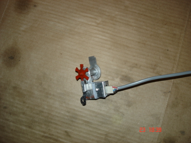
so how long will it last?
02GF74 - 24/4/08 at 09:52 AM
Finally completed and fitted my speedo sensor.
Wired up to speedo and by spinning one rear wheel, the speedo needle is between the 0 and 10 mph so is showing promise.
Was not able to dermine the gearing in the gearbox speedo take off so will need to go driving in order to calibrate speedo.
Previous prototype survived so this one looks like it should last a fair bit but .......
Too many hours spend on this but satisfying now it is done. (next time I thnk I'll fork out the £ 60 even though it is against the locost - diy
philosopy)


Rescued attachment DSC03571.JPG
worX - 24/4/08 at 09:57 AM
Not sure how long it'll last but it looks pretty good. And even though you'd shell out next time, it's still satisfying to know that
you've made one at least once!
Steve
Mr Whippy - 24/4/08 at 10:01 AM
It'll need a cover surely to stop dirt covering the optics, not sure how you’ve connected it to the wheel.
02GF74 - 24/4/08 at 10:11 AM
there is a magnet one side of the chopper wheel and hall effect sensor on the other. The small box has some electronics to provide a pulse for the
speedo - I suspect I should have mounted this inside but was worried about the low level signal from the sensor.
I did consider optical but that would involve making a sealed unit that I do not have the ability to do.
my concerns are two fold: ingress of oil/water but there was a small gasket glued where the cable plugs in and rest is sealed using selaant - the grey
stuff.
and if the bearing wears, the chopper blades will wear down the sensor. 
there is a led on the small box to drop the voltage to the sender plus provide a visual that the sender is working.
DarrenW - 24/4/08 at 02:44 PM
I cant help thinking you have just re-invented the wheel. Looks good but in my book some things are meant to be bought.
02GF74 - 28/4/08 at 10:11 AM
quote:
Originally posted by DarrenW
I cant help thinking you have just re-invented the wheel. Looks good but in my book some things are meant to be bought.
... but one could say the same about a chassis and other thing too....
I am not sure I have the space to fit geatbox adapter and sensor and did not want to use sensor using propshaft bolts.
So far so good so the 5 people who predicted it would last less than 1 mile - ya boo sucks to you!!
A spin on the motorway with 60 mph showing on bike speedo allowed me to calibrate it - was underreading by 5 % so pretty good first guess!!

