
throttle bods
theconrodkid - 28/5/06 at 07:49 AM
ive got gsxr bods for my zetec.
a few probs that i see are the lack of pressure reg and finding some tube to extend fuel rail when i split the bods.
could i use the zetec fuel rail and injectors just using the bods for air control?
what have peeps done to connect throttle linkage after splitting the bods as the levers will have a gap between them?
Dusty - 28/5/06 at 08:33 AM
I have just gone this route and its a pain and needed a few favours. I used an ST170 manifold. Mig welded small extensions to the throttle tabs. A
friend machined alu top hat spacers to space the carbs and similar to space the fuel rail which another mate Tig welded. Took three shots to get that
fuel tight.
If I was doing it again I would get a custom manifold from Bogg bros or someone which did not space the bodies and accept the slightly bent outer two
tracts. Saves all the hassle and use the GSXR injectors which are I believe 275 for the 750 and 330 for the 1000. The zetec injectors don't flow
enough for any tuning.
(the ST170 injectors and rail are not connected at the moment)
[Edited on 28/5/06 by Dusty]
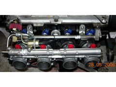

Rescued attachment DSCN0777.jpg
theconrodkid - 28/5/06 at 09:11 AM
aha see yours are different to mine,i have 3 ally tubes that feed the injectors,i was going to do away with them and use zetec fuel rail as it holds
injectors and has pressure reg as well.
ill not be doing any tuning,too old for all that speeding malarky
Krismc - 28/5/06 at 10:58 AM
there is no need to split the TB's ive got 750 ones and with a custom manifold they should be fine, plus i bought a adjustable fuel regulator
with guage for £45 for ebay


original injectors from tbs and mega squirt ecu if that helps???
[Edited on 28/5/06 by Krismc]
piddy - 28/5/06 at 05:08 PM
I contacted a chap who often sells complete GSZR bodies on zetec manifold and asked him if he could supply me with a extension kit and moded fuel
rail. They are on there way to me as I speak.
Extension kit £20
Fuel rail to take GSXR injectors at the correct spacing for the zetec £35.
Take a look at this link and then look in his feedback and look at what he has sold
recently.link
[Edited on 28/5/06 by piddy]
theconrodkid - 28/5/06 at 08:33 PM
cheers chaps,as an idea for mounting without spliting and cutting n shutting the inlet pipes,if i use 30deg bends and angle them up and inwards a
little i think i can get the spacing right.your thoughts please

Krismc - 29/5/06 at 08:29 AM
thats what im doing, saves splitting them
Krismc - 29/5/06 at 09:10 AM
Im not totally certain how but i was told i need to strip the second butterfly out (dont ask which one) and then have to attatch a throttle linkage
etc etc??
FiredragonCT - 29/5/06 at 10:37 AM
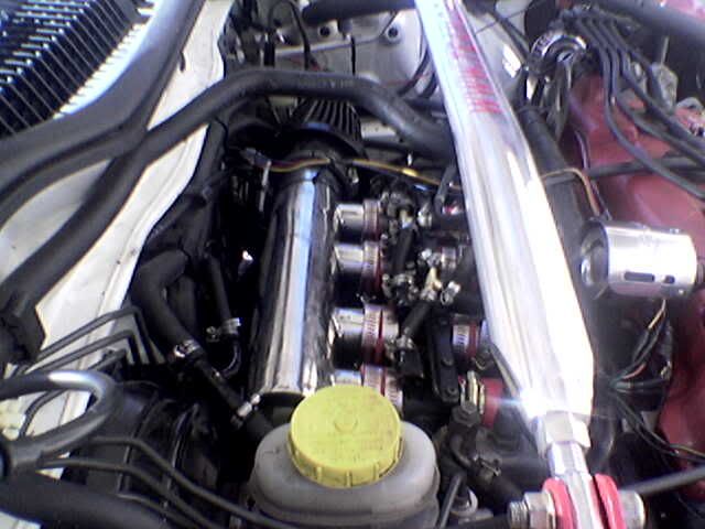
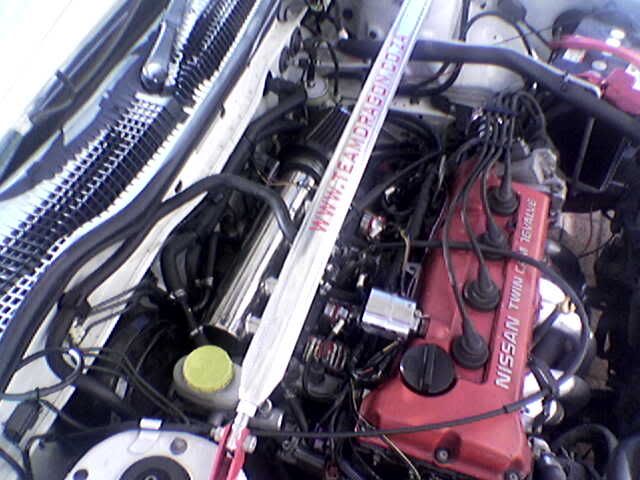
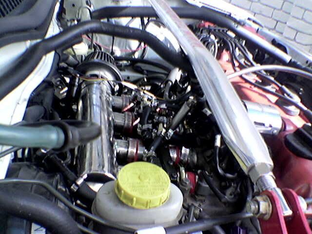
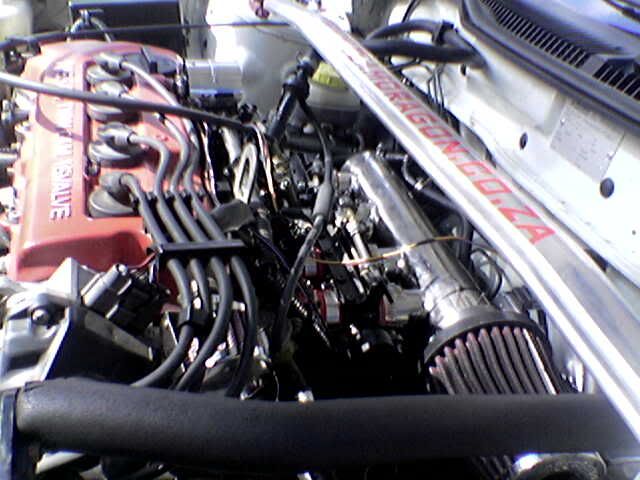
I recently fitted a set of GPZ1100 throttle bodies to a GA14 Nissan motor - but they differ from the ones shown above - they do not have injector
positions - this enabled me to use the standard intake manifold mountings, fuel rail, and pressure regulator - just had the intake pipes cut off and
modified to take the ITB's - are these sets available there as well?
Furthermore I adapted the Nissan TPS to fit onthe bodies and manufactured an accumilation box to mount the MAF sensor in - this work very well and
with minor adjustment ran very smoothe - some pics attached - hope this helps a bit!
First I took an old intake manigold (off the GA16 motor) and cut off the tubes a very short distance from the intake itself...
Next I had 4 runners made up to get the spacing right for the ITB's...
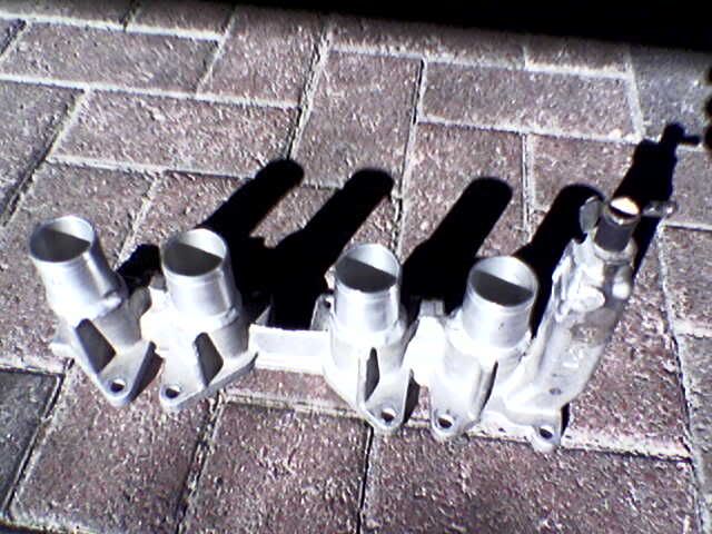
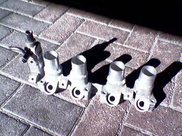
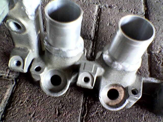
Some of the water jackets had to be slightly modified....
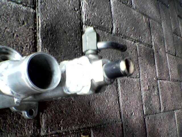
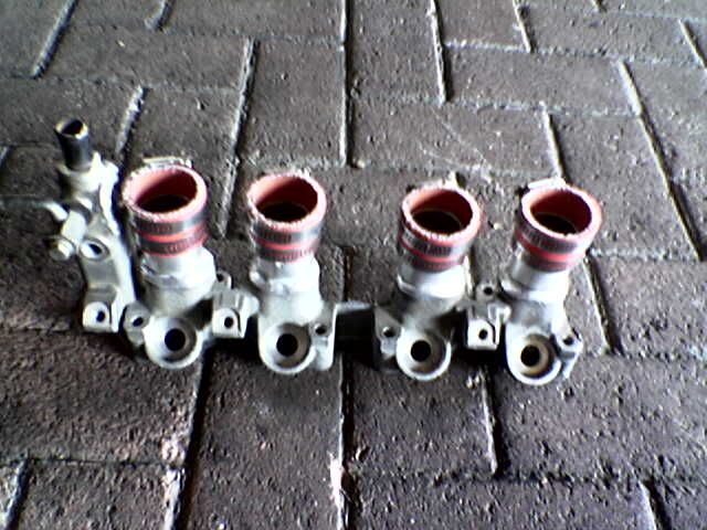
I chose to use the ITB's off a GPZ 1100 Kawazaki (35mm)
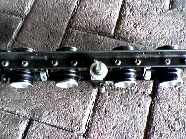
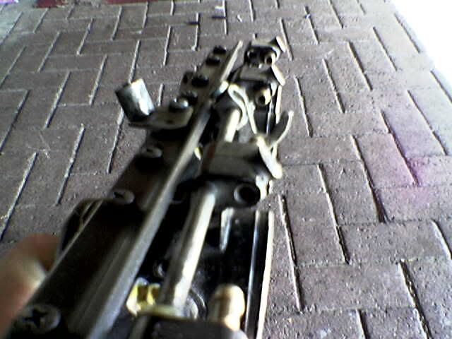
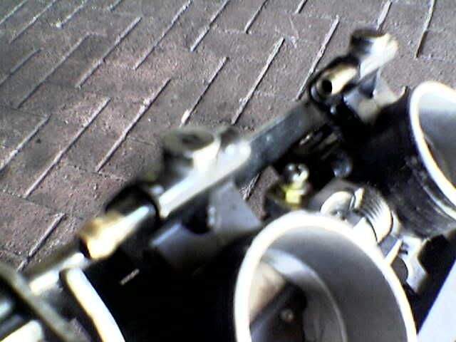
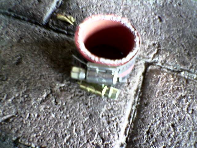
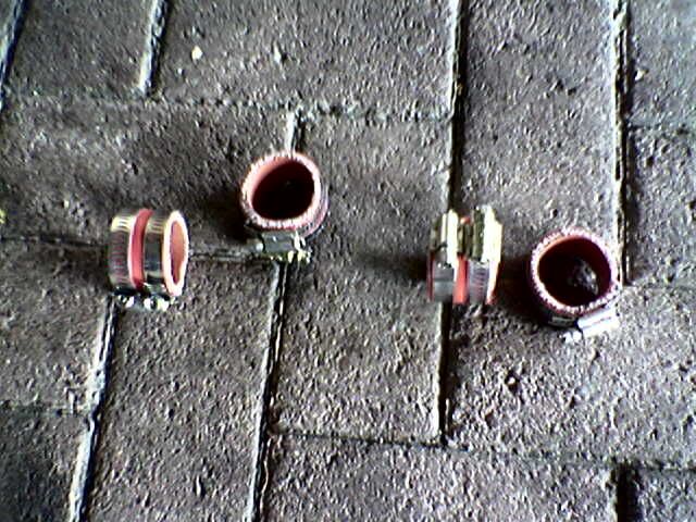
Silicone hose was used to link the ITB's to the intake manifold...
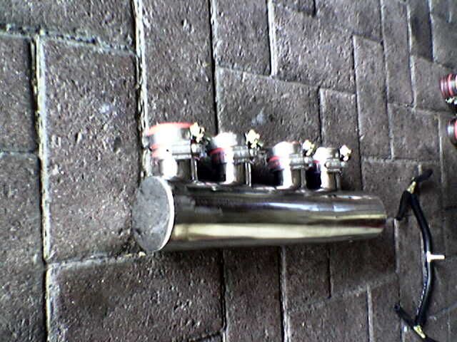
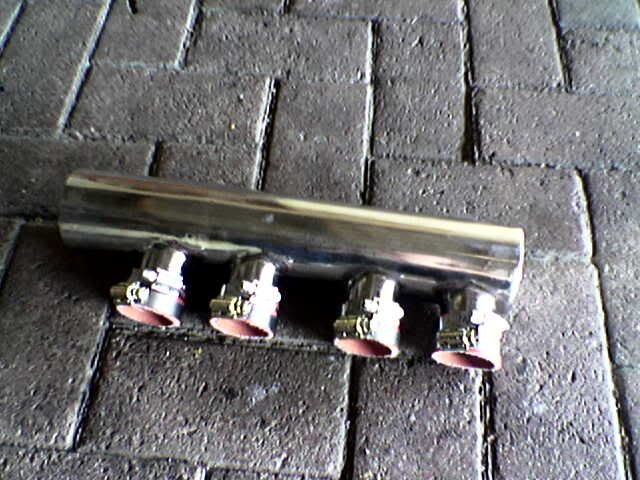
A Custom Stainless steel air-box was made up for me by Lizzard Engineering - thanx Dion!
All the brake vacuum lines were summated to supply adequite vacuum for the brake booster
So the assembly begins:
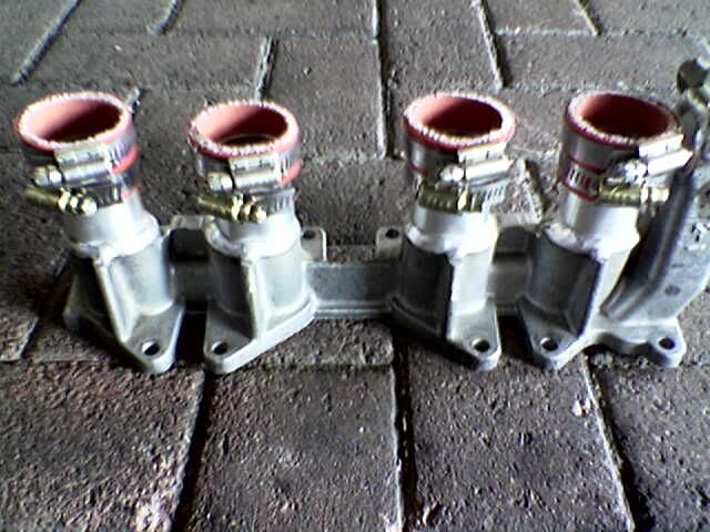
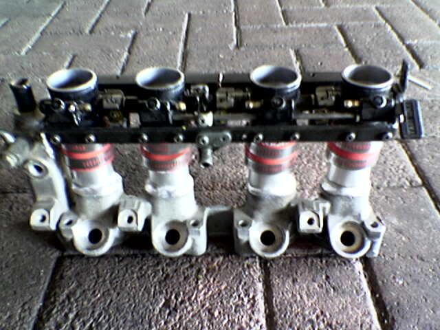
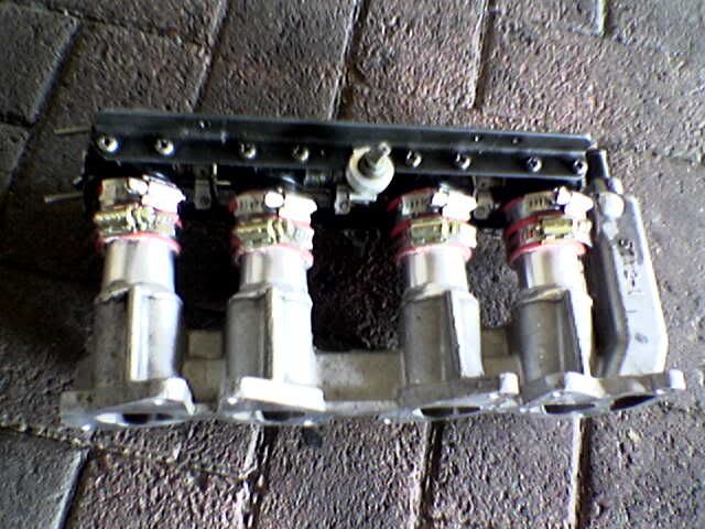
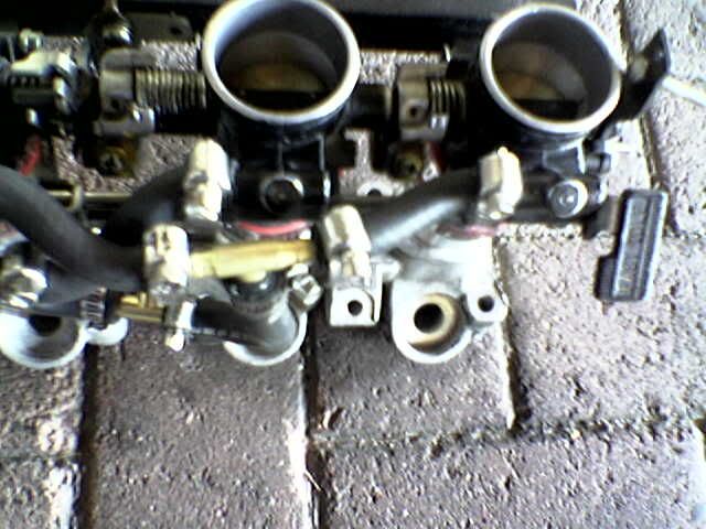
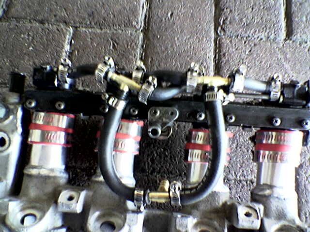
The standard Nissan Throttle Position Sensor was modified to fit and function with the Kawa ITB's
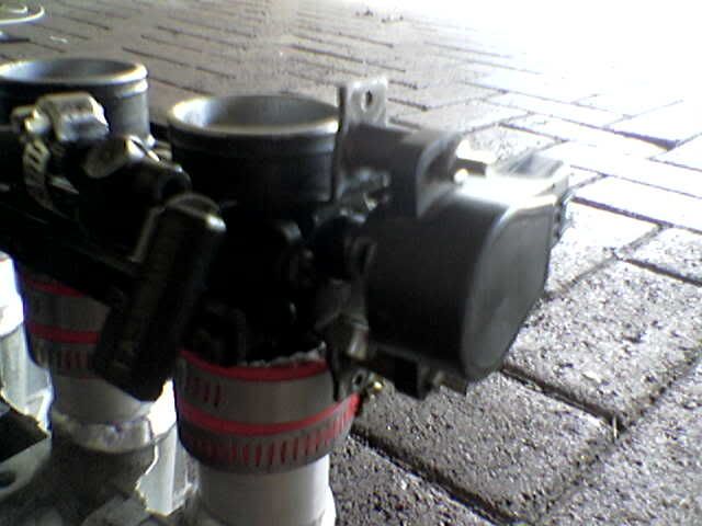
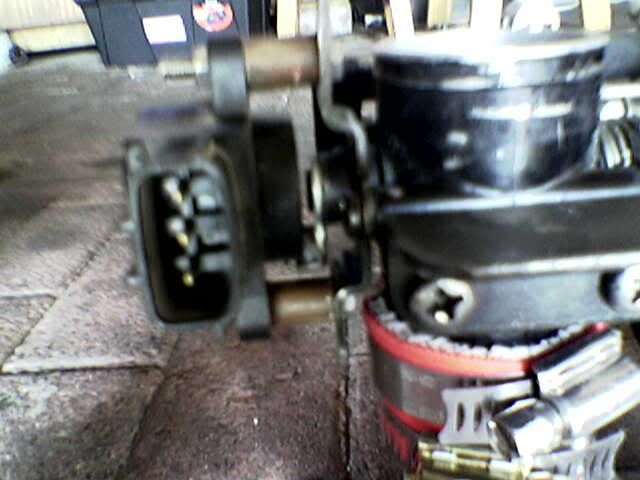
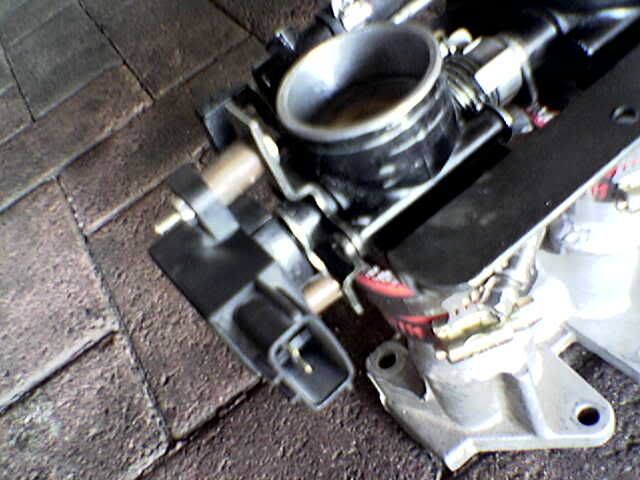
And there we go - all done!
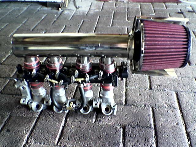
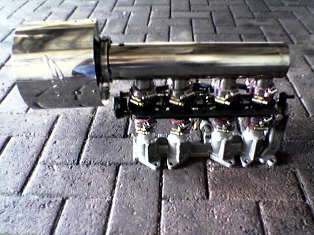
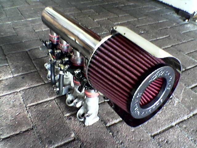
In the end I had to settle for a different air filter due to space restrictions.
I removed the Dastek Unichip and fitted the Perfect Power SMT6 - allthough the car started up and ran without any chip - Primary mapping is deen but
still needs lots of balancing and dyno tuning!
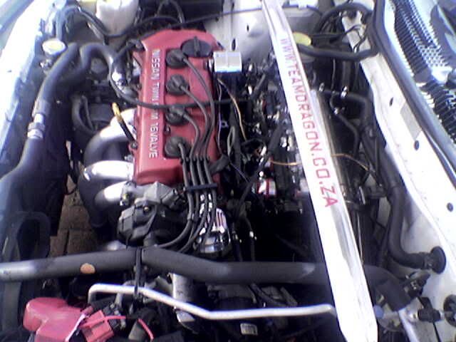
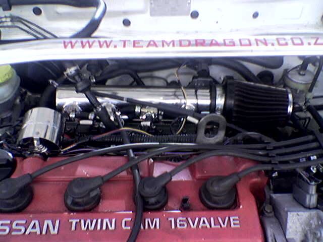
theconrodkid - 29/5/06 at 11:33 AM
the butterflies that need removing are the furthest from the engine side,driven by an electric motor,you have to split them to get spindle out.
when i find some plate that the dog seems to have stolen ill make the face plate and see how it pans out
ps mr dragon,looks real nice but i dont have a tig, only a big hammer and some bent screwdrivers
[Edited on 29/5/06 by theconrodkid]
Doofus - 1/6/06 at 10:28 AM
theconrodkid,
Sounds like you have the same bodies I have. I did mine the locost/lotech method.
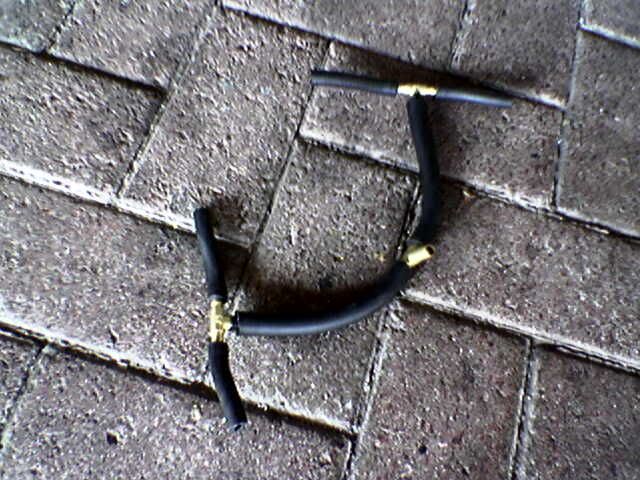
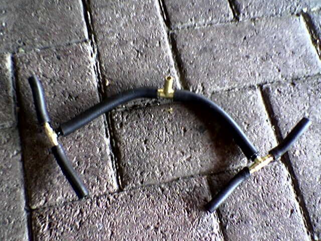
Spaced them using washers and longer threaded bar. Bent the throttle linkages by hand and cut and shut the ally tubes using fuel hose.

Luckily I had 2 sets of bodies and used 2 feed pipes as the supply and return from the rail then used a conventional FSE pressure reg.
Another car I've seen has some ally T pieces to replace the feed/supply connectors (because I nicked his for my car ;-) )
Another friend has gone the ST170 manifold route and used the injectors and regulator in the plastic ST170 moulding, like Dusty, and he'll be
starting his soon so I'll keep an eye on the duty cycles there.
Paul.


