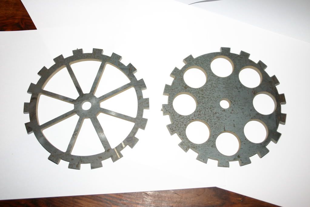
not sure what one to use...
both 6mm mild steel.....

thanks mr lardarse for the drawings...


so i cut two two trigger wheels...
not sure what one to use...
both 6mm mild steel.....

thanks mr lardarse for the drawings...
er, what ignition system?
i'd go with the one on the right myself
Not much of an expert Barry, but I reckon the one on the right loks a little more substantial. Not sure what flexing can occur in the other one?
Either way, good job 
JB
blake.....its a megajolt....
john...i like my traction engine one
those trigger wheels wont work with MJ 
http://trigger-wheels.com/store/index1.html
[Edited on 30/3/10 by cd.thomson]
for mega jolt it should be 36 teeth (with 1 missing) if its with ford edis
think it needs a few more teeth 
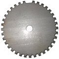
a bit like this

[Edited on 30/3/10 by blakep82]
quote:
Originally posted by boggle
john...i like my traction engine one

bollocks....
anyone got a drawing or sizes of what i do need???
pictures on the link I posted boggle 
hmm, not really, but basically needs to be equally size teeth and gaps. 36 of them (so a tooth every 10 degrees) and 1 of the teeth is missing (so you actaully end up with 35 on the wheel)
need the tooth sizes, land, root diameter and overall diamter.....
can anyone help with these???
you won't be able to put this in the machine, but


Description
the size of the teeth will depend on the diameter of the wheel. that picture is the one i used to have mine made, and mine works. just copy that and
scale it up or down to what you need
so diameter is unimportant?? just the amount of teeth?
basically yeah. the risk is, if you go too small, the teeth may not give a strong signal, but if you do it the same size as your crank pulley for
example, it should work just fine
i say the same size, but i made the teeth stick beyond the edge of the pulley to make sure the sensor didn't pick up on the pulley itself
ok...thats what i shall do...cheers blake....
maybe a smiley face on this one???
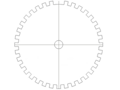
I've got a cad drawing somewhere that should do it - have you got an e-mail ? (u2u it to me if you don't want it public)
[Edited on 30/3/10 by mcerd1]
you have u2u..
thank you
if you can get a diameter where 1 tooth completely coveres the head of the sensor, then perfect, but still make sure the teeth are the same width of the gaps
my drawing is just based on equal sizes of spaces / teeth, the one tooth removed
that will be fine....anything to help....
you should have it now.........
It's a shame that you can't use either of them, I personally prefer the look of the left wheel, would have thought that at 6mm it would be substantial enough. Hope you get it sorted.
Drawing sent Barry 
I've also done a simplified 2D *.dxf (attached if anyone wants it)
its 5.125" dia. (~130mm) and has a 12mm hole in the middle