paulbeyer
|
| posted on 10/9/04 at 10:03 AM |

|
|
quote:
Originally posted by Peteff
Will you be concreting the yard soon Pete? In the words of Fred West, " I'm just measuring the wife up for a new patio"
I could tell you a lot of stories about Fred, Rosemary and 25 Cromwell Street  I was a Consultant for the the murder inquiry. I was a Consultant for the the murder inquiry. 
7 out of 10 people suffer with hemorrhoids. Does that mean the other 3 enjoy them?
|
|
|
|
|
James
|
| posted on 10/9/04 at 10:52 AM |
|
|
In what field did you consult? Thought you did Telelcomms?
Cheers,
James
|
|
|
pbura
|
| posted on 10/9/04 at 12:43 PM |
|
|
Quite a pair the Wests were:
http://www.thisisgloucestershire.co.uk/displayNode.jsp?nodeId=147046&command=newPage
Old Fred was a real DIY type. Potential Locost builder?????
Could this thread have traveled any further OT?
Back to Joel's pics, it's hard to see how the rear subframe is attached to the chassis and how loads are directed. About all that's
visible is the rear diff attachment, which IMO doesn't look very strong if that's the only mounting point.
My frame of reference is the Tiger style IRS, in which the diff sits in a box that is fairly well tied to the rear bulkhead and the shock towers.
Not pretending for an instant to know anything about structures, btw. Just can't see how you did it, Joel. Mind highlighting the pertinent
tubes with Paint or something? If you can't be arsed that's fine
Pete
|
|
|
liam.mccaffrey
|
| posted on 10/9/04 at 05:35 PM |
|
|
why should he have to paint his chassis and take more pictures just so you can see how its done? 
Build Blog
Build Photo Album
|
|
|
pbura
|
| posted on 10/9/04 at 06:03 PM |
|
|
quote:
Originally posted by liam.mccaffrey
why should he have to paint his chassis and take more pictures just so you can see how its done?
LOL
Well, he WAS looking for opinions, wasn't he? You know that opinions are like @$$holes, everybody has one. I'm having difficulty
rendering my own idle speculations unless the lad jumps through a hoop or two
Pete
|
|
|
JoelP
|
| posted on 10/9/04 at 07:09 PM |
|
|
will do pete, gimme a few hours and i'll pull something out of the hat...
|
|
|
stephen_gusterson
|
| posted on 10/9/04 at 07:46 PM |
|
|
pete
this was a very famous set of murders in the UK a wile back. you will find much about it on the internet. Fred West to the UK is like Bundy in the
USA.
cept we didnt fry the f&*ker, he killed himself. Which is just as well, cos with our system, hed be in his own cell watching tv right now. Just
like all the poor young girls he killed are not.
Some were raped as they suffocated with a plastic bag over their head. Nasty little bit of work.
atb
steve
quote:
Originally posted by pbura
Quite a pair the Wests were:
http://www.thisisgloucestershire.co.uk/displayNode.jsp?nodeId=147046&command=newPage
Old Fred was a real DIY type. Potential Locost builder?????
Could this thread have traveled any further OT?
Back to Joel's pics, it's hard to see how the rear subframe is attached to the chassis and how loads are directed. About all that's
visible is the rear diff attachment, which IMO doesn't look very strong if that's the only mounting point.
My frame of reference is the Tiger style IRS, in which the diff sits in a box that is fairly well tied to the rear bulkhead and the shock towers.
Not pretending for an instant to know anything about structures, btw. Just can't see how you did it, Joel. Mind highlighting the pertinent
tubes with Paint or something? If you can't be arsed that's fine
|
|
|
JoelP
|
| posted on 10/9/04 at 08:10 PM |
|
|
his own daughter too...
|
|
|
JoelP
|
| posted on 10/9/04 at 10:49 PM |
|
|
anyway, back on topic!
heres a close up of the shocker mount. maybe needs modifying.small.jpg)
|
|
|
JoelP
|
| posted on 10/9/04 at 10:50 PM |
|
|
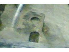
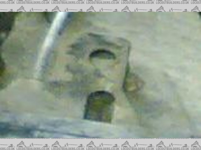
heres the diff back mount. pretty much the same as in the donor, minus the rubber
bit.small.jpg)
|
|
|
JoelP
|
| posted on 10/9/04 at 10:52 PM |
|
|
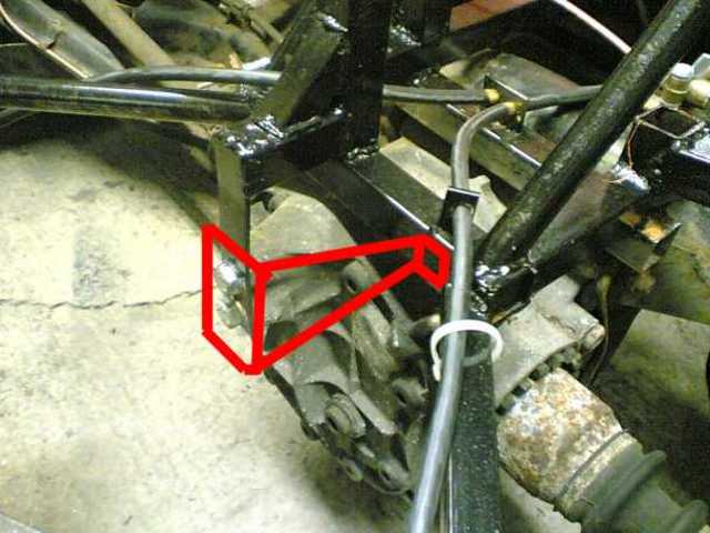
heres the subframe mount, showing the force during acceleration. remember its only a 1.6 pinto! not triangulated but the panel is welded and its only
2 inches above the fully welded floor, and each side is attached to two
uprights.small.jpg)
|
|
|
JoelP
|
| posted on 10/9/04 at 10:53 PM |
|
|
and finally, the force that matter. the weight of the car and the reaction of the shocker. not perfect but adequate i think.
|
|
|
JoelP
|
| posted on 10/9/04 at 10:54 PM |
|
|
damn, attachments and beer dont mix...small.jpg)
|
|
|
stephen_gusterson
|
| posted on 10/9/04 at 11:20 PM |
|
|
joel
the acelleration forces will be applied at the diff mounts, not at the front of the subframe.....
thats if im seeing your pictures correctly. If you think about it, the diff would like to rotate, instead of the drive shafts / wheels. The swinging
arm is just kinda hanging there keeping the wheel in place. However, when you apply brakes, the swinging arm will be subjected to a rearwards and
downwards force, as applying the brakes will tend to try and take the swing arem with the hubs.....
atb
steve
|
|
|
pbura
|
| posted on 11/9/04 at 01:19 AM |
|
|
Considering Mr. G's remarks about braking forces, I'd be concerned about the subframe trying to pull itself rearward during braking.
Suggestion: 3mm plates on top and bottom of your subframe mounts to spread the loads a bit more.
Also with regard to your diff wanting to rotate, all that's restraining it is a longish vertical tab that might be prone to fatigue. Suggest a
belt-and-suspenders approach, maybe 2mm steel?
Rescued attachment untitled.jpg
Pete
|
|
|
pbura
|
| posted on 11/9/04 at 01:23 AM |
|
|
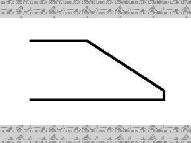
If you want to have longer shockers (or firmer springs on the ones you have), I see nothing wrong with putting the mounting bracket on a gusset
between yiour support tubes:
Rescued attachment untitled2.jpg
Pete
|
|
|
JoelP
|
| posted on 11/9/04 at 07:36 AM |
|
|
could be an idea!
a couple of points though. the diff is attached the the full subframe remember! the little bar only holds it in place vertically, same as the donor.
there will be no twisting force on it beyond what is allowed by the two rubber mounts for the subframe.
also, though i hate to disagree, the acceleration is from the wheel, the wheel pushes the swinging arm, which pushes the subframe, which pushes the
car! if you removed the swing arm the wheel would roll forward without the car.
i like the idea of the gusset though, so i will look into it.
ps, the rubber bit has a 3mm plate for the bottom, similar to donor part but flat. thats getting added as soon as i take the back end off!
[Edited on 11/9/04 by JoelP]
|
|
|
pbura
|
| posted on 11/9/04 at 12:48 PM |
|
|
quote:
Originally posted by JoelP
remember! the little bar only holds it in place vertically, same as the donor. there will be no twisting force on it beyond what is allowed by the two
rubber mounts for the subframe.
Doh! I rather missed the forest with that one.
Re: the subframe mounts, are you comfortable that the subframe cannot be pulled out under braking? Can't see clearly, but it looks to me like
the mounts are a "C" shape with weld built up on the inside to make a bolt hole. That's why I suggested plates top and bottom, because
rocking of the bolt might tear up the relatively thin-walled tubing on the 3 sides and/or eventually pop out the weld. I may be wrong about this.
It looks like you're in for a job making bodywork for the rear end. I don't think the usual Seven-style box would look very good because of
the size of it. Got any ideas? How about sort of a wedge shape? Top would be open like a regular Seven:
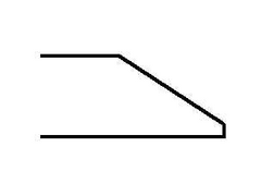 
Rescued attachment untitled.jpg
Pete
|
|
|
MikeRJ
|
| posted on 11/9/04 at 05:20 PM |
|
|
quote:
Originally posted by stephen_gusterson
joel
the acelleration forces will be applied at the diff mounts, not at the front of the subframe.....
The only forces the diff mounts will see are reaction forces from the torque being transmitted through the propshaft and the driveshafts (i.e. the
diff will want to twist in the same direction as the propshaft and in the opposite direction to the driveshafts).
All longitudinal forces from acceleration & braking forces will be applied to the car through the wishbones, the subframe amount and then into the
subframe/chassis mounting points.
Joel, I think traingulating the front mounting points would definately be a good idea, even if it strong enough when the car is static there will be
high cyclic loads through this mountong as the car hits bumps etc. and it could cause fatigue failure.
Personaly I would also have made the two diagonal tubes on each side out of 25mm section. They are supporting the weight of the car, and the
relatively narrow round tube will be more prone to buckling over the fairly long lengths you have.
Out of interest, how much ground clearance do you have under the subframe mounts? I know the Robin Hoods tend to be pretty low at that point.
[Edited on 11/9/04 by MikeRJ]
|
|
|
MikeRJ
|
| posted on 11/9/04 at 06:17 PM |
|
|
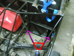
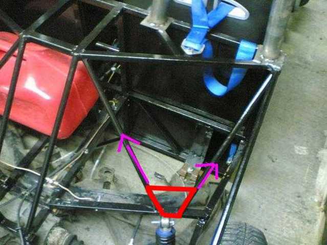
Looking at the back end more closely, a lot of the forces are being fed into the rectangular structure at the top/middle of the picture. However,
there is nothing present to direct these forces into the main structure except the welds where the rectangular section is joined to the top tube of
the bulkhead. Some triangulation here is essential I'd have thought, something like the following:

|
|
|
Northy
|
| posted on 11/9/04 at 07:20 PM |
|
|
Joel, you've built a beast!
Graham
Website under construction. Help greatfully received as I don't really know what I'm doing!
"If a man says something in the woods and there are no women there, is he still wrong?"
Built 2L 8 Valve Vx Powered Avon
|
|
|
JoelP
|
| posted on 11/9/04 at 08:16 PM |
|
|
a monster graham!
longer answers in 10 mins, im off for a pizza! thanks for the input guys.
|
|
|
JoelP
|
| posted on 11/9/04 at 08:37 PM |
|
|
ok guys, here we go!
pete. the bit that the subframe mounts to is actually stronger than it looks. in short, it is three inch square tubes side by side, fully welded. the
middle one is shorter,and in the end there is a small vertical piece of inch square. across the top at this point is a 3inch x 25mm x 3mm strip, with
a bolt hole thru the middle. this is what the frame bolts to. on the bottom, a large 3mm plate holds the other end of the bolt.
i think triangulating it is a good idea, not because i think there is any chance of an instant failure, but to reduce stress fatigue due to constant
flexing.
mike, there is 4 inches under this point, same as the rest of the car. i might raise the entire car, but 4 inches isnt too far off ok IMO.
Syd, you are entirely correct. this actually occured to me the other day. gonna have to work out how to include the rubber bit on the back. dont worry
about me taking offence, your opinions are always worth hearing even if you are a funny bugger with some people! (joking, of course.):p
pete, as for the shape of the back end, i am considering just glueing ply onto it to get it thru the test, then making some fibreglass to do it
properly. the shape will be much as you suggest, just following the bars.
oh yeah, mike, the extra bar you suggest is both needed and exactly what i want to do - but on the n/s it would collide with the fuel tank. i've
thought long and hard about how to do it, but to no avail. the price of not planning i guess. also, i need to work out the braces for the roll bar,
without buggering the rear bodywork. (good photoshopping, BTW!)
still, not too much left now. and at least i can drive it around the yard!
[Edited on 11/9/04 by JoelP]
|
|
|
Mark Allanson
|
| posted on 11/9/04 at 09:15 PM |
|
|
Joel, just a thought, but if you move the shock upper brackets underneath the attached rail, and connect your fwd subframe mounts to the new shock
mounts and continue this rearward to the rear subframe mounts, you will create a perfect triangle with the shock transmittiong the load to the right
place. The subframe will make the bottom of the triangle.
Are you going to hook up the inner fwd subframe mounts?
Mark
If you can keep you head, whilst all others around you are losing theirs, you are not fully aware of the situation
|
|
|
JoelP
|
| posted on 11/9/04 at 09:20 PM |
|
|
by forward subframe mount, do you mean this? on the donor it doesnt attach to anything.
Rescued attachment untitled.JPG
|
|
|


