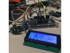
Megasquirt Data Logger / Display with GPS
AntonUK - 11/11/16 at 01:52 PM
Hi All,
This one is a little car related project I've been working on a while, but during my week off I've managed to finish it. It just needs
mounting a proper box and installing into the car.
The system takes a serial feed from the megasquirt (msextra v2) to process and then display selected valued on an dash mounted 20*4 LCD. In addition
to the LCD there is a small 1" OLED to be mounted on the steering column that displays speed, rpm and fuel level. Speed is taken from a GPS
receiver built in.
All values can be logged to the SD card too.
I'm quite pleased with it... any comments or suggestions. Possible mods I've about is G-force data, Bluetooth connectivity and ability to
log max/min values.


Datalogger
Huttojb - 11/11/16 at 03:08 PM
Hey Anton
I'm doing the same sort of thing on my build, nearly finished myself, we definitely need to exchange notes.
What Micro and compiler you using?
Huttojb - 11/11/16 at 03:09 PM
Actually I can see, looks like an UNO.
AntonUK - 11/11/16 at 03:34 PM
its running on a Arduino mega 2560 as i ran into memory issues with the UNO, code has since shrunk but the additional hardware serial's are
useful so sticking with the Mega.
Are you interfacing via CAN or serial to the ECU? I couldn't get the CANbus working.
locost@mintynet.com - 11/11/16 at 10:07 PM
Hi Gents,
Im building a similar device.
Originally built for MS1 using the serial 9600 comms, Arduino Mega, Neo 6M GPS, DS3231 RTC, SDLogger, 2 x 20x4 LCD, XYZ Accelerometer, Neo Pixel
(RPM/Satelite Indicator), physical button array.
I have upgraded it to communicate with the MS2 CPU using a MCP2515 CAN BUS adaptor (leaving the COM port on the MS2 to be used for Autotune/Logging),
the biggest problem with CANBUS was to terminate the MCP2515, I have also added a 2.8" Nextion Serial controlled display and removed the physical
button array. I have still to work out how to send data from the Arduino to the MS2 over CANBUS.
Have a look at the Nextion displays for showing data.
Have a look at my website on the link below.
http://mintynet.7host.com/?len=9999&date=20161110
Any question please feel free to ask.
Regards
Ian
[Edited on 11/11/16 by locost@mintynet.com]
AntonUK - 11/11/16 at 10:22 PM
Id be interested to see your code/setup for the MCP2515, I could not get anything from it?
locost@mintynet.com - 11/11/16 at 10:49 PM
Drop me a U2U with your email details and I'll email over my code, there are still a few bugs but I will try to explain them.
Huttojb - 12/11/16 at 08:58 AM
Hey Anton.
I have my kit car running on the CANbus and most of the electrics are now operating on the CANbus with 4 nodes now fitted to my car. I can give you my
test code and Basic breadboard layout. When building the nodes I do the Core breadboard layout and then load my test code to ensure CAN and the micro
work correctly, then I add the require electronics around it.
I do use Microchip PIC18F4680 with the C18 compiler, if your interested I can send you the Core board data and code.
Also if you fancy visiting I be happy to show you what I've done. Ive been meaning to make some videos over the last few days because I want to
post the build so far and see what other members think. I know that it might be frowned at but I want to write about my reasoning.
I do want to put a GLCD on with possible a PIC32 driving it with the new environment but never done a LCD before so just getting the core electrics
done. The good thing about CAN is you can easiler add a node after and just keep growing. But I will explain all this in my post about it ( when I can
be bothered to video it )
locost@mintynet.com - 12/11/16 at 10:11 AM
Jason
Where in the country are you located? I would like to have a look.
Thanks
Ian
Huttojb - 12/11/16 at 11:37 AM
Sunny Birmingham.
Huttojb - 14/11/16 at 01:05 PM
Where you located Ian?


