the_fbi
|
| posted on 3/10/06 at 09:54 PM |

|
|
Thick moment on dash switch wiring
I've been up too long and I just can't think straight, so perhaps not the best time to be looking at my dash wiring, but.....
I've got illuminated switches for main beam and fog (as per left hand pic from VWP below)

They have 3 connections lets say a, b, c.
I've checked with a meter and b and c are permanently linked. So naturally a is switched to both when switched.
Any clues as to how this should be wired?
Presumably feed to a then return to b. So whats the use of c?
I've not stuck it on 12v yet but I presume that the light will light with just a and b connected and the switch on, but perhaps not.
Any clues?
ta
Chris
|
|
|
|
|
DIY Si
|
| posted on 3/10/06 at 09:59 PM |
|
|
I'd have expected the live in for the switch, live out from switch and maybe an earth from the lamp. Or live in for switch, live in for lamp and
common out? Or earth for lamp and live from switch out, with live for switch in. Or something else I haven't though of!
Let your plans be dark and as impenetratable as night, and when you move, fall like a thunderbolt.
Sun Tzu, The Art of War
My new blog: http://spritecave.blogspot.co.uk/
|
|
|
the_fbi
|
| posted on 3/10/06 at 10:02 PM |
|
|
I did consider
a = live in
b = live out
c = -ve (ground)
so that the light has a ground for when the live out is on. But the light would ground through the live out and live in anyway, same as the actual
light would.
Although perhaps that would dim both lights?
What I have realised is that whatever these 3 connections are for, they are fine for the fogs, but the main beam needs 2 "on" positions,
one for the headlight and the other for the main beam.
Bum 
|
|
|
Macbeast
|
| posted on 4/10/06 at 07:15 AM |
|
|
At a guess...
a - +ve feed
b - +ve switched out to heads
c - earth (chassis, -ve)
You may be seeing continuity b - c through the low resistance filament of the internal lamp.
|
|
|
the_fbi
|
| posted on 4/10/06 at 07:19 AM |
|
|
quote:
Originally posted by Macbeast
At a guess...
a - +ve feed
b - +ve switched out to heads
c - earth (chassis, -ve)
You may be seeing continuity b - c through the low resistance filament of the internal lamp.
I considered this, but why isn't the switch's light just inline with a or b anyway? It doesn't need an earth as it'll earth
back through the main light anway.
Or is it because both lights (switch light and the one being switched) would be half as bright if the switch isn't earthed?
|
|
|
Macbeast
|
| posted on 4/10/06 at 07:41 AM |
|
|
Your headlamp, or whatever, is connected between the switched 12V and earth, so the current runs through the switch through the bulb and down to
earth.
An indicator lamp should be connected in parallel with the main bulb, ie between the switched output and earth as above.
It is not earthed through the main bulb - that would be a series connection, not parallel, - and the indicator lamp would light but the main bulb
would be starved.
If you connect two similar 12V bulbs in series you would get just 6V across each and the bulbs would be dim.
Hope this helps - well it doesn't help with the main/dip problem where I think you might have to have two switches (or a 3-way switch ) and two
separate indicator lights

|
|
|
02GF74
|
| posted on 4/10/06 at 09:48 AM |
|
|
quote:
Originally posted by the_fbi
I've checked with a meter and b and c are permanently linked.
I have to question ^^^^ that bit.
If both b and c are common, why not have 1 terminal instead of two?
What meter are you using? I suspect you are measuring the low resistance of the bulb that makes you think they are connected - are you using a DVM
set to the lowest range?
Anyway, for the witch to do its business, i.e. connect your load to 12 V and have the bulb illuminating, the bulb must be parallel.
So unless I am mistaken, the internals have to look something like this:
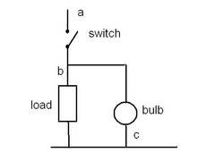 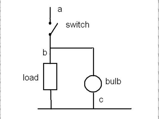
switch
You should be able to take it apart as the bulb should be replaceable - that will give you insight on what is going on inside the switch. Or contact
VWP for a circuit diagram!!
|
|
|
MikeRJ
|
| posted on 4/10/06 at 10:30 AM |
|
|
quote:
Originally posted by the_fbi
I considered this, but why isn't the switch's light just inline with a or b anyway? It doesn't need an earth as it'll earth
back through the main light anway.
Because that would never work. In that situation you would have a small low wattage (high resiatance) lamp connected in series with a high wattage
(low resiatnce bulb). When switched on, the vast majority of the voltage would be dropped accross the small lamp, so although the switch would
illuminate, your fog/headlamps would not.
I would agree with the conclusions reached above, i.e. conecctions are most likely
a +ve feed
b +ve switched
c ground for illumination lamp
Check that b & c are correct though, if you get the wires crossed on these you will blow a fuse (or melt wiring if no fuse in the circuit!). With
the switch closed, measure resistance between a & b and then a & c using a multimeter set to it's lowest resistance range.
If a & b gives you a higher resistance (shoud be about 50-100ohms) then b is the lamp ground, otherwise c is.
|
|
|
the_fbi
|
| posted on 4/10/06 at 06:37 PM |
|
|
quote:
Originally posted by Macbeast
It is not earthed through the main bulb - that would be a series connection, not parallel, - and the indicator lamp would light but the main bulb
would be starved.
If you connect two similar 12V bulbs in series you would get just 6V across each and the bulbs would be dim.
Hope this helps - well it doesn't help with the main/dip problem where I think you might have to have two switches (or a 3-way switch ) and two
separate indicator lights
Exactly the same conclusion I came to and it appears everybody else too.
On the main/dip issue I'm going to use a 5 pin (SPDT) relay to switch off the headlights and on the main beam.
Thanks all
|
|
|