RazMan
|
| posted on 1/3/06 at 08:05 PM |

|
|
Sierra Indicator Switch Question
While wiring up the switch I notice that there are two wires running to the flasher relay (Black/red & Black/white) My LED flasher only needs two
connections (power & load) If I connect the black/white wire to the flasher relay everything works except the hazard warning light on the column.
The black/red doesn't seem to change anything.
Am I missing something? Is the warning light connected internally? What does the black/red wire do?
As always, any help is appreciated 
[Edited on 1-3-06 by RazMan]
Cheers,
Raz
When thinking outside the box doesn't work any more, it's time to build a new box
|
|
|
|
|
Peteff
|
| posted on 1/3/06 at 09:53 PM |
|
|
If you have the later column switches the rd/bk connects 49a on the switch to 49a on the flasher relay to power the hazards. The bk/w(terminal 49)
carries power to the left and right indicator from the flasher relay depending which way the stalk is moved. Have you got a permanent live feed (red)
to terminal 30 on the switch to power the flasher and light the warning light.
[Edited on 1/3/06 by Peteff]
yours, Pete
I went into the RSPCA office the other day. It was so small you could hardly swing a cat in there.
|
|
|
RazMan
|
| posted on 1/3/06 at 10:15 PM |
|
|
There are two black/whites on my switches
L - left indicators (black/white)
49a - flasher relay (black/white)
R - right indicators (black/green)
Confusing eh?
My loom has a common feed to the relays so I guess the red wire isn't needed for getting power to the flasher but maybe needed for the warning
light.
My Evodash will flash both indicator warning lamps so do I need the column one for SVA?
[Edited on 2-3-06 by RazMan]
Cheers,
Raz
When thinking outside the box doesn't work any more, it's time to build a new box
|
|
|
Peteff
|
| posted on 2/3/06 at 10:49 AM |
|
|
do I need the column one for SVA?
No, as long as something tells you the hazards are operating, your dash lights will do.
yours, Pete
I went into the RSPCA office the other day. It was so small you could hardly swing a cat in there.
|
|
|
RazMan
|
| posted on 2/3/06 at 10:54 AM |
|
|
Cheers Pete, I was thinking about moving the switch to the dash and smoothing the column shroud anyway.
Cheers,
Raz
When thinking outside the box doesn't work any more, it's time to build a new box
|
|
|
RazMan
|
| posted on 2/3/06 at 11:26 AM |
|
|
Update:
Pete, I was just going over your post again - I think I got the wrong end of the stick.
My flasher relay is presently fed by a switched feed along with all the other relays - this is where my problem lies.
If I make the flasher relay feed independently from the black/red wire it should allow my hazards to work with the ignition off.
Cheers,
Raz
When thinking outside the box doesn't work any more, it's time to build a new box
|
|
|
Peteff
|
| posted on 2/3/06 at 01:46 PM |
|
|
It has to work with the ignition on or off, that's why you need the red permanent live to the terminal 30 as well as the black switched live to
terminal 54 which carries the power via the bk/rd on terminal 49 on the flasher relay. The bk/gn wire to terminal C is the switched live feed to the
flasher relay. The bk/w is bringing power back from the flasher via 49a to the indicator stalk and bk/w is also used for the left circuit. Bk/gn is
used to feed the flasher and is also used for the right circuit. If you don't use the original switch you will need to connect the two circuits
for them to flash together as this is done inside the hazard switch.
[Edited on 2/3/06 by Peteff]
[Edited on 2/3/06 by Peteff]
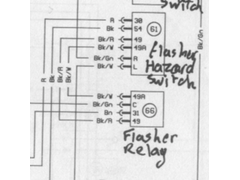 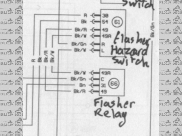
Rescued attachment flasher.jpg
yours, Pete
I went into the RSPCA office the other day. It was so small you could hardly swing a cat in there.
|
|
|
RazMan
|
| posted on 2/3/06 at 10:13 PM |
|
|
Very clearly described Pete - thank you. I've now got everything flashing when it should...... and I think I will leave the hazard switch where
it is - too much work to move it.
Now I've just got all the other switches to sort out 
Cheers,
Raz
When thinking outside the box doesn't work any more, it's time to build a new box
|
|
|


