omega 24 v6
|
| posted on 8/1/06 at 12:13 PM |

|
|
Relays
Can some one explain the different applications where you would use the types of relays fitted with diodes and resistors across the coils.
As I undrstand it the diode is to do away with the backword emf voltage which can be quite high and destroy delicate electronics. The resistor variant
I'm not so sure about but think it's for screening interference from TV'S Radio's etc.
|
|
|
|
|
steve_gus
|
| posted on 8/1/06 at 12:56 PM |
|
|
I am an electronics designer, and unless resistors across coils are specific to the car industry for some reason, i dont know of such types (and none
were fitted to my donor). I dont know what the purpose of it would be.
Some things on a car might look like a relay, and have a relay in them, but may actually be a controller, such as a wiper speed controller.
The coil itself has a resistance, as would any electrical circuit. Is this the 'resistor'?
The diode, as you say, is used to 'clamp' back EMF from the coil. It can prevent circuit damage (on very delicate electronics) but in most
cases is used to prevent a 'spike' that might upset other electrical equipment, such would be the case if the relay is operated by a
computer. The spike would otherwise travel back into the computer and may cause it to crash.
If the relay is used in a 'conventional' circuit where the current only flows in one direction, then there will be no downside to using a
relay with a diode in it. However, it WILL matter which way around it is connected. If you reverse it, the diode will conduct and act as a short.
You can tell what type yopu have with an ohmmeter. A diode version will give a different reading if you reverse the meter leads, one with no diode
will read same both directions.
atb
steve
http://www.locostbuilder.co.uk
Just knock off the 's'!
|
|
|
omega 24 v6
|
| posted on 8/1/06 at 01:21 PM |
|
|
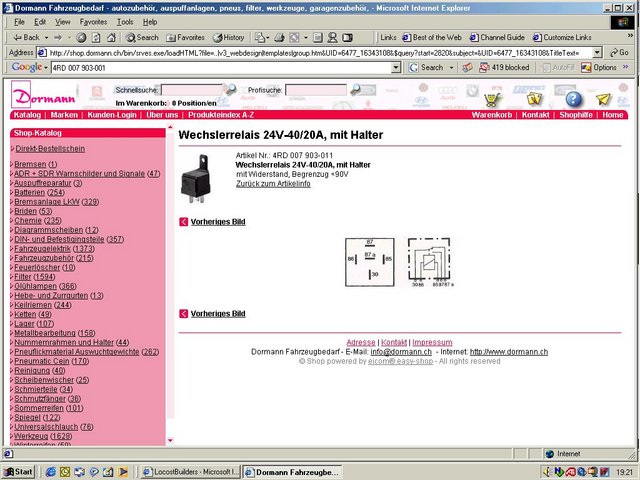
I have used the diode type before and understand the advantages but the resistor tyoes I'm not to sure about there is one you can look at on the
hella website part no 4RD 007 903-001. It is shown as a parrallel resistor.
|
|
|
madman280
|
| posted on 8/1/06 at 04:15 PM |
|
|
The resistor performs the exact same funtion as a diode. Clamps voltage spikes induced by the changing magnetic field in the coil. Most modern cars
use them now. Voltage spikes cause all kinds of problems with computerized modules.
I fitted a methonal water injection unit recently to a Ford Super Duty 4WD truck. I used the relay supplied with the kit. No diode no resistor. Every
time the turbo boost switch activated the system, the speedometer went to zero, all the dash warning lights came on, then the engine stalled. Hardly
the big power boost the owner wanted. After measureing the injection system output and double checking the wires, all I had to do was change the
relay. Nice set-up now..scarey how a 2 ton truck can squeal all four tires and suck you back in the seat though.
|
|
|
silex
|
| posted on 8/1/06 at 04:27 PM |
|
|
As Madman explained, the resistor and diode perform the same basic function.
However, just out of general interest the resistor works better than a diode.
Murphy's 2 laws
1. If it can go wrong it will
2. In case of emergency - refer to rule 1.
|
|
|
steve_gus
|
| posted on 8/1/06 at 07:09 PM |
|
|
I cant see that part on the site.
I also dont understand how a resistor would work better than a diode.
A diode works on the basis that when the EMF occurs, the diode will forward conduct, and effectively 'clamp' the spike to a volt or less.
(if you use a shottky diode it can be even less - this would be the best type to use).
A resistor is merely a passive device that that would perhaps work to 'damp' any back emf by acting as a load as the coil begins to create
back emf. This wont serve to 'clamp' but merely to attenuate.
All the PCB level electronics ive seen prefer to use diodes rather than a resistor - in fact i dont ever think ive seen a resistor on its own. It
wouldnt be very power efficient as the resistor will draw current whenever the relay is on - the diode will normally be reversed biased and will draw
no current until the back emf occurs.
Its fairly normal to use capacitors and resistors used in series to 'damp' overshoot caused in switching, (usually across contacts).
At the end of the day it depends what the application is. If you are switching headlights from an control stalk, it wont matter. If its something from
an ECU then it may.
Ue of a resistor may be more down to cost reduction.
Here is a link to a chip that would typically be used to drive relays (inductive loads). Note that the manufacturer chose to use a diode at each
output which would effectively be connected across the load when in circuit.
http://www.electronelec.co.uk/uln2803a.htm
atb
steve
[Edited on 8/1/06 by steve_gus]
http://www.locostbuilder.co.uk
Just knock off the 's'!
|
|
|
steve_gus
|
| posted on 8/1/06 at 07:19 PM |
|
|
ok
found it
the circuit diagram of the device shows no resistor....
however, translating the description
Maximum stress (with +80°C). With owner and flattening hitting a corner connections 6,3mm and bypass resistor.
so thats all clear then 
atb
steve
[Edited on 8/1/06 by steve_gus]
Rescued attachment relay1.jpg
http://www.locostbuilder.co.uk
Just knock off the 's'!
|
|
|
steve_gus
|
| posted on 8/1/06 at 07:28 PM |
|
|
The relay has a brother
4RD 007 903-021
this specifically states :
Maximum stress (with +80°C). Without owners, with diode. Inductive noise crash is prevented by the diode. Plus potential at flat pin 86.
the piccy clearly shows a diode across 85 and 86.
ayb
steve
 
Rescued attachment diode2.jpg
http://www.locostbuilder.co.uk
Just knock off the 's'!
|
|
|
omega 24 v6
|
| posted on 8/1/06 at 10:18 PM |
|
|
Mmm thats not how the one on the hella site is depicted.
go to http//www.hella.co.uk
or hopefully this picture will load
http://www.locostbuilders.co.uk/photos.php?action=showphoto&photo=XQ_pWGyRHXLMrG3t3FjQtgU161.jpg
you can see the parrallel resistor now.
It seems strange to have two different ways to acheive the same thing unless it's a cost issue and if so why not make them all the cheapest
way.
[Edited on 8/1/06 by omega 24 v6]
|
|
|
paulf
|
| posted on 8/1/06 at 10:39 PM |
|
|
Ive ocasionally come across this on industrial equipment and it was used more often years ago, before silicon diodes were cheap.I would have thought
that it may be a voltage dependent resistor that is used nowadays.
Paul.
|
|
|
silex
|
| posted on 9/1/06 at 06:15 AM |
|
|
steve_gus I can't explain exactly why the resistor is better than the diode, I'm not an electronics engineer. All I know is that Hella
kept on pushing it too us at work so we tested our electrical system comparing diode and resistive protection and there was an improvement using the
resistor versions.
We dropped the diode on all relays and now use resistors throughout.
Murphy's 2 laws
1. If it can go wrong it will
2. In case of emergency - refer to rule 1.
|
|
|
steve_gus
|
| posted on 9/1/06 at 12:59 PM |
|
|
its reasonably academic cost wise - the price for 1 off a single diode or single resistor works out at 1p or less resistor, 3p or less diode!
A resitor is likely to have an effect - but I dont see how its better than a diode as
1. the resistor will always draw current when the relay is on - which is a bit wasteful
2. The diode has a precise cut off point and will clamp any pulse rather than seek to supress it by acting as a damping load.
3. In my experience its much more usual to use a diode than a resistor (again, never seen a practical example of a resistor in this mode, but I admit
I havnt looked specifically for it!)
There is often more than one solution to an engineering problem, it may be that both resistor and diode have merits.
When the supply to an inductive load is removed, the magnetic field in the coil colapses, which is in effect 'stored charge'. This engergy
will attempt to 'jump the gap' of any switch that opened the circuit in an effort to find a discharge path. The resistor will be acting as
a load to continue a circuit across the coil to allow it to discharge without any 'gap jumping'. The diode will act as a 'shorting
clamp' across the coil which activates as the reverse current flow throu the coil occurs as the field collapses. This turns the (normally
reverse biased) diode on, dissipating the charge.
atb
steve
http://www.locostbuilder.co.uk
Just knock off the 's'!
|
|
|


.jpg)
