ReMan
|
| posted on 17/7/05 at 11:28 PM |

|
|
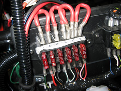
Linking fusebox feeds
See picture. I did this temporarily whilst I was testing my loom. The loops are to supply each fuse from battery and switched from ignition. On a
production car this would be taken care of by linking the fuse unit with solid plates
Now it works OK and i'm just finishing wrapping it , i'd like to make a better job? even though it won't be seen once the scuttle and
dash are on.
Any ideas?
Rescued attachment fuses.jpg
www.plusnine.co.uk
|
|
|
|
|
Hellfire
|
| posted on 18/7/05 at 12:35 AM |
|
|
Now I'm no electrician... but, I'd say if fuse 6 was drawing it's full capacity as were all the rest then wire 1 would draw 20 amps
max. BUT wire 3 and male connectors need's to be capable of handling 30 Amps... I do not think the connectors are designed to handle this much
current - they are afterall only a thin bit of metal - it's not the wire that is the weak point it's the connector blades your using.
I'd take them back down the wire and join (SOLDER) them from there....
That's my opinion - but like I say, I'm no electrician!

|
|
|
Ham
|
| posted on 18/7/05 at 08:49 AM |
|
|
That seems fine as current is measured in series and the loops are connected in parallel therefore, if loop 6 is drawing 10 A it does not mean that
loop 1 is seeing the same current. I.e. the max current drawn by each loop will be limited by the fuse, I am pretty sure that the connectors used are
rated over 10 A
Cheers
|
|
|
ReMan
|
| posted on 18/7/05 at 09:30 AM |
|
|
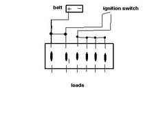
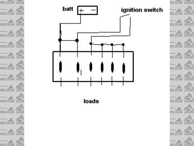
Here is a VERY BAD diagram of whats going on here.
I "was" fairly confident that the connectors would take the current, but its difficult to find a definative spec which says say 20A max, but
you gan get them (the yellow ones)for up to 6mm cable which is about 50 amp I think.
The most current being drawn from one terminal would be that which is drawn through an individual fuse, as the wires are looped the current going down
the line to feed the other fuses is not all going through the blade connector. The loops are made of thicker wire than the original battery feed
(Hellfire I am sure you recognise this as the Fireblade fusebox equivelant).
I suppose I could make the loops out of a single thick core, like mains wire and solder them?
Cheers
Rescued attachment fusediag.jpg
www.plusnine.co.uk
|
|
|
lsdweb
|
| posted on 18/7/05 at 12:57 PM |
|
|
Reman
I've used your method on previous cars with no problems although the concerns relating to loading are justified.
I'd be careful if you consider soldering bridges in as you could melt the fuse box - trust me!
On my current car, I took a length of battery cable (multistranded) and split the strands into six different bundles and shrink wrapped all these -
this gives one feed from the master switch to six different points on the fuse box - it works well but took some time!
I could take photos but I'd have to strip the scuttle off etc.
Regards
Wyn
|
|
|