Hugh_
|
| posted on 19/2/09 at 11:41 PM |

|
|
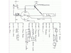
Wiring diagram, does this look right?
 
Wiring?
I was going to use to CBS Wiring module for this bit, but it seems a bit of a waste of money so thought I'd at least have a go at a wiring
diagram for it. Does this look right?
Will the ignition warning light (LED) work when wired in parallel like that? The other (not ideal) option would be to leave it out and set one of the
user options on MegaJolt to voltage, at say 13v and wire that to the battery indicator on the Bright 6.
|
|
|
|
|
RK
|
| posted on 20/2/09 at 12:04 AM |

|
|
This is coming from someone who has no actual experience, except with Austin Healey ownership 20 years ago. I'm just giving opinion,
understand.
BUT, that looks a lot like my first wiring of my dash - that I am now going to change. I was told though, that it would be safer to wire the (+)
directly to the fan, lights etc, and the NEG back from the device to the corresponding switch. The NEG from the switch then goes to the chassis, and
when closed, completing the circuit. This apparently reduces the chance of a short in the switch itself, with resulting dire consequences.
Your method has the (+) going right to the switches does it not?
|
|
|
ReMan
|
| posted on 20/2/09 at 12:36 AM |

|
|
It looks pretty ok to me.
There's a bit more to it when you add in any relays plus the switches etc but as the feed/power section it should work
Personally I wouuld have all the lights except indicators off the permanent live but that's minor
|
|
|
theconrodkid
|
| posted on 20/2/09 at 07:42 AM |

|
|
put the coling fan feed straight to battery then seperate fuse,everything else can go to ign,i would use a relay for ign fed fuse box feed ie try not
to put too many loads through one switch,use relays where poss
who cares who wins
pass the pork pies
|
|
|
Mr Whippy
|
| posted on 20/2/09 at 08:04 AM |

|
|
quote:
Originally posted by theconrodkid
put the coling fan feed straight to battery then seperate fuse,everything else can go to ign,i would use a relay for ign fed fuse box feed ie try not
to put too many loads through one switch,use relays where poss
Its a good idea to use the relays instead of the switch handling loads like headlights, done it both ways on cars but most production cars use the
relay method (you can hear them clicking on) and I'm sure that would be more reliable over time.
Fame is when your old car is plastered all over the internet
|
|
|
Hugh_
|
| posted on 20/2/09 at 08:16 AM |

|
|
Thanks guys. I was planning on using the relays for beam, dipped, indicators and hazards, its just a bit complicated to show on 1 diagram when hand
drawing so left them out. I presume the switch within the key barrel can take the load, or should I wire the permanent live fuse box straight to the
battery with an inline fuse?
|
|
|
02GF74
|
| posted on 20/2/09 at 08:42 AM |

|
|
3 comments
- where is the low brake fluid/test lamp/switch?
- fuse between battery and starter?!?!??!  That is gonn have to be a bout 200 A; I am not aware of there being a fuse there but a fat wire. That is gonn have to be a bout 200 A; I am not aware of there being a fuse there but a fat wire.
- is D+ the winding field for the alternator? this should be fed with volts from the battery in order to self-excite. I take it you have a LED there
- it is wired wrong way round as you will not feed the alternator plus the lamp will never come on.
A LED would be wired other way round plus you need a 3 W 68 ohm resistor wired in parrallrallel for the feed. (maplins sell them for 30 p or so)
|
|
|
Mr Whippy
|
| posted on 20/2/09 at 10:16 AM |

|
|
although most production cars don't fuse the starter motor cable you can easily and quite cheaply use one of these just incase the cable rubs
against the engine/body etc and shorts the battery. They go all the way up to 500amps so quite suitable.

he’s got D+ fed from the ignition key so that will start the alternator charging but like you say the diode is the wrong way round though but it is
shown wired in parallel
[Edited on 20/2/09 by Mr Whippy]
Fame is when your old car is plastered all over the internet
|
|
|
dhutch
|
| posted on 20/2/09 at 12:11 PM |

|
|
quote:
Originally posted by Mr WhippyIts a good idea to use the relays instead of the switch handling loads like headlights, done it both ways
on cars but most production cars use the relay method (you can hear them clicking on) and I'm sure that would be more reliable over time.
Yeah i would ditto.
- Ive been watching these threads so see whats commonly done after my three-position side/dipped switch got a little soft inside (in a controled
fashion).
- The switch is rated for 25A and measure calulate the load is about 12A (An fused at 20A) buts still softened, proberbly due to dirty contacts.
- The Dipped/main toggle works with a relay, but the side/main switch still takes all the power first.
The cables to the headlights are also a tiny bit underspeced as well i think. Fine for the current, but the voltage drop over them is a volt or so.
Although this is proberbly fairly common.
Daniel
|
|
|
02GF74
|
| posted on 20/2/09 at 02:23 PM |

|
|
quote:
Originally posted by Mr Whippy
he’s got D+ fed from the ignition key so that will start the alternator charging but like you say the diode is the wrong way round though but it is
shown wired in parallel
in parrallel with a piece fo wire?!?!?! that ain't gonna work.,
|
|
|
Hugh_
|
| posted on 20/2/09 at 02:55 PM |

|
|
Any suggestions on how to use an LED as a Ignition warning light then?
|
|
|
Hugh_
|
| posted on 21/2/09 at 01:02 AM |

|
|
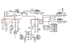
I've spent the evening amalgamating my many different diagrams into this. Where switches can be moved to the negative side of components without
having to run massively more cable I have included it, I'm still undecided on whether it is worth running all the extra cable to wire everything
that way.
The changes are basically limited to:
- A master switch, as I'm not happy leaving the majority of the circuit permanently live (and it will replace the master fuse mentioned earlier
in this thread),
- LED warning lights, which I'm still not sure about?
 
Wiring Diagram
|
|
|


