
R1 5PW Wiring Question
Pdlewis - 12/5/08 at 09:06 AM
Hello,
Would anyone have a picture / document which tells you the what each ECU wire is for (by pin number)? I have been dissmembering my loom as it wasnt
complete when i got it and have a white wire which goes from the starter relay to the ECU but i can work out which ECU pin it attaches to as I have
identified most of them now.
Also is the air temp sensor an import part of the system? (as im missing it) 
ko_racer - 12/5/08 at 09:18 AM
I've only got the Yamaha wiring diagram which I'd guess you already have. Not quite sure what the white wire does but at a gues I'd
say it's the permananet ecu feed.
Might be worth phoning Yamaha tech and asking them what pin it goes to. The number is the yamaha head office one, just ask for tech dept. They can
sometimes be quite helpfull.
What do you need to know the pin for? Have you taken the ecu connector apart?
Pdlewis - 12/5/08 at 09:22 AM
No ive not taken it to bits but one of the wires (the one I think it is) has a connector attached to it and almost none of the original cable so i
cant tell if its the right colour
worX - 12/5/08 at 10:33 AM
Have you identified your Oil Level Sender wire yet?
Steve
markyb - 12/5/08 at 11:08 AM
I have started the wiring on my R1 and am using this as my guide.
According to the site the air temp sensor (number 26) is required by the ECU but does not say why.
I dont have a clue about electric so hopefully someone else will be along to help
[Edited on 12/5/08 by markyb]
CRAIGR - 12/5/08 at 11:48 AM
Not sure if this will help
http://dsr.racer.net/engines/yamaha_yzfr1.htm
nstrug - 12/5/08 at 12:17 PM
http://www.robcollingridge.com/kitcar/design/engine/WiringDiagram.pdf
http://www.robcollingridge.com/kitcar/design/engine/Haynes_R1_2003.jpg
You should be able to identify where the white wire goes from the first diagram (which is the workshop manual one). It is needed as this is actually
the power for the ECU (taken from the injection fuse side of the starter solenoid).
The air temp sensor is definitely needed as it is used by the ECU, along with manifold air pressure sensor and ambient air pressure sensor to
calculate the air density.
Air density, throttle position and RPM are then used to calculate injector opening.
The ECU also uses coolant temp to moderate the injector opening (basically to enrich at startup).
Note also that you MUST have the speed sensor connected, even if you aren't using it. Its used by the ignition circuit.
Basically, you must have all sensors connected EXCEPT for the oil level sensor and EXUP actuator, which you can safely ditch.
I really recommend that you buy the workshop manual, which some bloke sells on CD on ebay. It has an excellent explanation as to how the ECU uses all
the inputs, as well as comprehensive wiring diagrams.
I used everything except the oil level sensor (didn't fit with my baffle) and the EXUP (which I ditched). I used a Digidash which came with its
own oil pressure, oil temp and water temp sensors and put those in.
Nick
Jubal - 12/5/08 at 12:44 PM
Here's the pins:
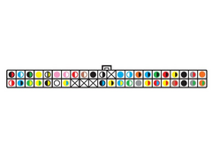
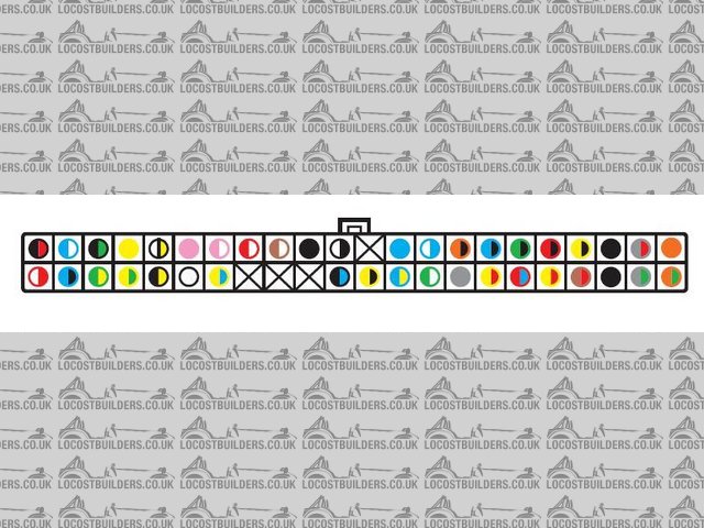
Rescued attachment ecu.jpg
progers - 12/5/08 at 01:48 PM
Hi There,
Drop me a line at progers63@btopenworld.com and I will send you a document that describes the ECU pins complete with diagram
Cheers
Paul
[Edited on 12/5/08 by progers]
