
Wiring frustration
DaveFJ - 30/5/07 at 11:03 AM
Got really frustrated last night... merrily wiring in my instruments and switches to the tiger loom.
Naturally none of the connectors fitted my non-standard instruments or switch gear so cutting away and re-crimping and also adding wires where
neccessary.
Got to the last instrument and was having some difficulty identifying the wires so I got out the multimeter...
 Just to find that I now have continuity between the Ign Live and earth!
Have started going through disconnecting everything in turn to see if it is the source but gave up in disgust after an hour and went for a
drink
Grrrrrr
I know - you can't help, I just have to work through it - Just wanted to vent my spleen....
[Edited on 30/5/07 by DaveFJ]
stevec - 30/5/07 at 11:22 AM
Are you sure its a dead short and not just a resistance through something harmless.
Steve.
omega 24 v6 - 30/5/07 at 11:22 AM
You will get a reading to earth through the ign live if it's connected to any device like a coil or motor or bulb etc. what you should be worried
about is what that reading is i.e. if its a dead short or just a combination of resistances.
DaveFJ - 30/5/07 at 11:28 AM
I get a short to earth even with ignition off completely. Have disconnected every wire outside the 'cockpit' area so they are ruled out.
have disconnected every wire on the megasquirt and alarm....
so all that's left connected are the handbake switch, the light switches and the instruments....
I'm sure(hope) the fault will be obvious when seen through a fresh pair of eyes this evening...
Just worried that I may have cocked up somewhere when splicing in wires which are now buried in the loom somewhere...
02GF74 - 30/5/07 at 11:33 AM
... probably a bit late now but I would suggest fitting one item at a time and testing it as you go along ... should you get a short at any time, then
it narrows it down to the last item wired.
don't be tempted by connecting a battery - the shorted wire will burn itself out but depending where it is, damage the loom in the process.
nitram38 - 30/5/07 at 11:35 AM
With a continuity check, any circuit will show as a "short" even if there is a correctly wired load on the end of it. You really need to use
an ohmeter as shorts will tend to show up as 0 ohms (or close to).
A little tip for testing you loom before connecting a battery is to buy a cheap battery charger and use that.
Obviously you can't test high power circuits, but you can check most things without risking high fault currents that a battery will supply.
flak monkey - 30/5/07 at 11:36 AM
Oh dear, its always a pain to find a short, especially if you have wrapped the loom.
Just work methodically through each connector and see if you can find which wires are shorted in each one, this should narrow down the possibilities
somewhat.
My moneys on the lights as they can be an arse. Simple though the circuit may be.
omega 24 v6 - 30/5/07 at 11:36 AM
quote:
I get a short to earth even with ignition off completely.
But where are you metering?? is the coil still connected??
As you say sometimes it's better to walk away and look another day. It'll be a process of elimination as you say then. Have you got various
earth points on the chassis with everything going to them or just random earths?? if it's the first then try removing the earths until the faults
gone. It may be quicker than checking every feed wire. At least that way you'll know which leg of the loom it MAY be in i.e if you remove the
rear light earths and the shorts gone it's a better place to start looking.
Edited to say that you could be getting a reading through the h/brake warning light to the switch???
[Edited on 30/5/07 by omega 24 v6]
nib1980 - 30/5/07 at 11:46 AM
lucky you, I've been wiring up, and discovered that half the loom follows the french style, of all one colour black. 27 wires. all black.
i'm relying on luck at the minute!
DaveFJ - 30/5/07 at 11:46 AM
as I say - all lights / coil etc are disconnected.....

I am now thinking that maybe I have connected the intrument lighting circuit to the light switch incorrectly as the way it is now the lights on the
instruments will be permanently on (not that it would work I know but for the sake of argument)
Basically I am getting continuity across the +ve and -ve wires to the instrument lights and on to the chassis earth and also to the Ign live to the
instruments....
will check tonight to see what sort of resistances i am seeing. But first job is to rip out the light switch itself and see what happens (it was a
b*****d to fit!)
[Edited on 30/5/07 by DaveFJ]
omega 24 v6 - 30/5/07 at 11:54 AM
quote:
Basically I am getting continuity across the +ve and -ve wires to the instrument lights and also to the Ign live to the instruments....
But you will as long as any of the bulbs are lef5t in situ or any other device that is connected to earth is left in this line or any line it's
connected to that has a device in it.
As an earlier post said you need to look at ohms and not have it on beeper.
A tip from me before you do start ripping thing to bits would be to fit an inline fuse to the main battery pos post and then to the main wire (in
series) then fit say a 10 amp fuse (no more) connect up and if it blows you've got a short. Don't try and start the motor and don't
turn on any other equipment other than the circuit you think the faults in.
DaveFJ - 30/5/07 at 11:59 AM
so lights off and ignition off i should be able to measure contiuity from ignition live to earth? with NOTHING connected under the bonnet?
Oh bugger - just though about the Master cylinder fluid level detector.....
andrew.carwithen - 30/5/07 at 03:02 PM
quote:
Originally posted by DaveFJ
so lights off and ignition off i should be able to measure contiuity from ignition live to earth? with NOTHING connected under the bonnet?
Oh bugger - just though about the Master cylinder fluid level detector.....
How have you got the fluid level wired in?
It should just be switched to earth on the -ve side of the warning light (same as handbrake switch.)
I.E -ve from warning lamp to one terminal and other terminal connected to earth.
NOT (as i've seen done) +ve to one terminal and -ve to other! (meaning a dead short unless filled with brake fluid!)
DaveFJ - 30/5/07 at 03:10 PM
pretty sure I took a tap off the single wire that goes to the handbrake switch and ran that to the float switch then took the other terminal straight
to chassis earth - but I did that over 2 years ago so I can't be certain and now it's all hidden inside the loom somewhere...
andrew.carwithen - 30/5/07 at 03:21 PM
Certainly sounds as though you've connected it up right. Is the reservoir filled with brake fluid? (otherwise, obviously, it'll be making
permanent contact - but not the dead short you're looking for.)
DaveFJ - 30/5/07 at 03:26 PM
that was my thought before - cylinder is currently very low so it will be making contact......
do you have the Tiger 6fuse loom? if so do you know what the 2 black wires going to the speedo are for ? - they have different round type push on
connectors. I figure one must be earth but if the other is signal then where does the other end come out ?
[Edited on 30/5/07 by DaveFJ]
Schrodinger - 30/5/07 at 03:41 PM
Dave
My recolection of the Tiger loom is that the wires are for the illumination (standard speedo being mechanical)
I'm just off on holiday for a while or I would come and have a look at it with you.
DaveFJ - 30/5/07 at 03:43 PM
I have another wire for the illumination (thin red same as other dial lights) so I think that's out. cheers anyway
Have a good holiday
[Edited on 30/5/07 by DaveFJ]
andrew.carwithen - 30/5/07 at 05:49 PM
Dave, mine is the 6 fuse loom, but as stated previously, the loom is for a mechanical speedo. I've looked at all the wiring diags and legends
I've got for the Tiger loom and they only show wiring for illumination (i.e red and black wires for +ve and -ve. - nothing for an electronic
speedo sensor)
Not much help, I know, but I've got the same two black wires with different sized female bullet connectors. However, as I intend using the bike
clocks, they are redundant for my use anyway. (I can only think, perhaps, that Tiger supplied two different mechanical speedos with different earth
connectors on the back?)
If you are fitting an electronic speedo then you should have the appropriate sender to go with it which, unfortunately, you'll have to wire in
yourself.
DaveFJ - 30/5/07 at 08:32 PM
Well good news and bad news...
I have found the source of my problems
The switches that i bought at Stoneliegh seem to be .. knackered
Unfortunately they were from a stall where the bloke was flogging second hand parts recovered from the scrappy
plus side is they were cheap minus is they were the only ones I could find that I liked
On MUCH closer inspection they seem to have connectors missing and consequently I connected them wrong - connecting the negative for the switch
illumination to a terminal which was shorted to the main switch positive input
and, of course, I now have a hole in dash just the right size for these switches so i may just have to start all over
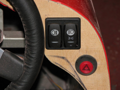
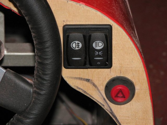
Here's a piccy of the switches I have - so if anyone can identify them I would be very grateful (oops apologies for the pic size!)
Description
[Edited on 30/5/07 by DaveFJ]
omega 24 v6 - 30/5/07 at 10:15 PM
Have you got a picture of the back of the switches???????
A lot of automotive switches are used to switch the earth side of a relay this could be what you're finding out with these. They look a nice
switch but I've not seen them before. How many terminals on the back of them??? Possibly the bottom slit illuminates as a tell tale to there
location and the symbol lights up when they are ON.
I don't know how UP you are on wiring and don't want to sound patronising but
If they are functioning then possibly they could still be used albeit with a bit of jiggery pokery and a relay. Don't give up yet unless
you're sure theyr'e fubared.
[Edited on 30/5/07 by omega 24 v6]
DaveFJ - 30/5/07 at 10:40 PM
the main light switch has 5 terminals on the back like this:
-
- -
- -
I now find that the middle 2 are shorted together. the bottom left is side lights and bottom right is dip so the middle 2 I figure are for the
+ve...
the top one doesn't seem to connect to anything and the 2 lights inside don't come on no matter what combination of connections I attach -
however I know they work because I managed to ease the casing open and test then directly....
omega 24 v6 - 30/5/07 at 10:51 PM
Any numbers on the terminals or surrounds?? any makers ID??
Very difficult from a long way away to sort this one out
omega 24 v6 - 30/5/07 at 11:11 PM
Are these the switches????http://www.carlingtech.com/pdf/CarlingSW_V4_5.pdf
If you think they are then look at this.diagrams
[Edited on 30/5/07 by omega 24 v6]
DaveFJ - 31/5/07 at 07:49 AM
WOW.. how did you find that??
yup these are definately the switches
Contura V....
now just got to decipher the diagrams etc to see what connectors should I have!
Cheers boyo
DaveFJ - 31/5/07 at 10:27 AM
Right - after looking at the documentation and much head scratching(on work time  )
)
I think I have the answer...
I think I have made a basic assumption about the switch which is incorrect... I don't now think it needs a +ve illumination input! I think that
is taken care of within the switch!
Also because they are LEDs I may not have been testing the connectors the correct way round!.. bugger...
I have a 8 pole type switch but only 5 poles are present of which 2 and 5 are shorted together. - like this:
.... _ 7
.... ....
_2xx_5
_3 _6
so if power is supplied 2/5 then in first position 2/5 and 3 are connected but 3 also goes through the illum LED to -ve on 7.
in second position 2/5 and 3 AND 2/5 and 6 are connected but 6 is also connected through the dip beam warning LED to -ve at 7
does that sound logical ?
[Edited on 31/5/07 by DaveFJ]
[Edited on 31/5/07 by DaveFJ]
omega 24 v6 - 31/5/07 at 11:34 AM
quote:
WOW.. how did you find that??
LOL trawled thriugh google images till I found something that looked like it may be them and the rest is history. I'll look at the diagrams later
on tonight and see if any of it makes sense.
DaveFJ - 31/5/07 at 11:48 AM
on the wiring diagrams - I figure the switch to be a 'G' and the lighting to be 'Special #1'
bearing in mind i don't have terminals 1,4 or 8.....
thanks for all your help BTW
[Edited on 31/5/07 by DaveFJ]
omega 24 v6 - 31/5/07 at 05:21 PM
OK I've studied the diagrams and I'd agree with your post. Goodluck connecting them up they're nice switches. And no problems I'm
glad to have been a help to you. Hopefully you'll have learnt quite a bit by the time you've finished wiring your car, it's not really
that black an art. but at times it can be frustrating.
DaveFJ - 31/5/07 at 08:47 PM
well - an evening well spent..
I tested the switches and my conclusions were correct BUT both LEDs had broken connectors on them!!!
So.. I found some LEDs the same size etc in an old PC case I had lying around. A bit of fiddling and soldering ... viola! the switches now work
perfectly and my odd earth short has gone
Thanks to all who contributed - especially omega24
[Edited on 31/5/07 by DaveFJ]
omega 24 v6 - 31/5/07 at 09:04 PM
SmugAint locostbuilders just the best. Well done.
[Edited on 31/5/07 by omega 24 v6]
