Connecting tacho to coil on plug positive feed
twybrow - 10/4/16 at 07:54 AM
Hi all. I am trying to sort a long term issue I have with stability of the RPM on my Koso R1XN. I had always used the tacho feed to the old bike
clocks (having tried alternatives as described below), but it is not stable. So I am starting from scratch with the feed. The instructions state to
connect to the cylinder 1+ve side of the CDI/coil. On my engine (ZX12R) it looks to me like the coils share a +ve feed, and are then triggered by the
ECU switching the earth.


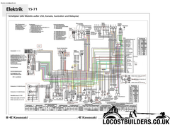
ZX12r wiring
Large wiring diagram
Is this correct? Please see the attached wiring diagram - should I be attaching to one of the red wires (labelled as Zundkerzen, at the top centre on
the German version of the wiring diagram I have!). I have had it set up to use the returning wire going back to the ECU from the spark, but reading
the Koso instructions, I think that this may be why I have been unable to get a stable RPM reading (as this is the -ve side of the coil). Help please
LCB collective!
[Edited on 10/4/16 by twybrow]
britishtrident - 10/4/16 at 08:23 AM
The +ve side of the coil voltage should normally show constant battery voltage apart from spikes.
The voltage on the negative side is the side the voltage will pulse on but because the ignition coil is an inductor in addition to the pulse at
battery voltage there is effect of the magnetic field collapsing which mirrors the ht tension spark voltage.
http://www.automotivetestsolutions.com/ignition-waveforms-tutorial-1.html
The cure is usually to fit a diode in-line in the wire from the coil to the tacho but
You could try this
http://www.hot-spark.com/tachometer-fix.pdf
[Edited on 10/4/16 by britishtrident]
twybrow - 10/4/16 at 08:44 AM
quote:
Originally posted by britishtrident
The +ve side of the coil voltage should normally show constant battery voltage apart from spikes.
The voltage on the negative side is the side the voltage will pulse on but because the ignition coil is an inductor in addition to the pulse at
battery voltage there is effect of the magnetic field collapsing which mirrors the ht tension spark voltage.
http://www.automotivetestsolutions.com/ignition-waveforms-tutorial-1.html
The cure is usually to fit a diode in-line in the wire from the coil to the tacho but
You could try this
http://www.hot-spark.com/tachometer-fix.pdf
[Edited on 10/4/16 by britishtrident]
Interesting, thanks BT. That pdf is actually how it is setup today (but this seems to go against conventional wisdom). I pull a feed from what I
believe is the -ve side of the coil and I have installed a step down resistor from that feed (one resistor feeding earth, one damping the tacho
signal), but so far it has not had the desired effect.
If I read you correctly, are you suggesting the +ve side wont be suitable to pull a tacho feed from as it will always be pinned at battery voltage of
12v? The very Chinglish instructions for the Koso are here and they seem adamant
I should be picking up on the +ve side....
big-vee-twin - 10/4/16 at 11:15 AM
The pdf does show the connection on the positive side (mines negative as BT says) have you tried wrapping a coil of wire around the ht lead like it
shows?
britishtrident - 10/4/16 at 12:25 PM
Just out of interest I connected my Owon Oscilloscope on the +ve of a coil pack on my tintop -- results pretty much as expected with the peak detect
turned lots of on noise. After I turned peak detect off there was only battery voltage with a few mV drop each time the coil was pulsed.
twybrow - 10/4/16 at 01:00 PM
quote:
Originally posted by big-vee-twin
The pdf does show the connection on the positive side (mines negative as BT says) have you tried wrapping a coil of wire around the ht lead like it
shows?
I don't have HT leads as my bike engine has coil on plug for the spark. So if I want to come off the coil, my options are either the +ve feed
(which BT suggests and logic agrees), or the -ve side of the coil which is in turn switched by the ECU, which is where I have had it previously.
If BTs oscilloscope test is anything to go by, I would say there is little point in running a wire from the +ve side of the coil to the Koso, which
leaves me once again with a wobbly tacho. I might try combinations of diodes and resistors next on the current setup....
dave_424 - 10/4/16 at 03:00 PM
Worth also trying the -ve wire on one of your injectors.
I was wiring in an innovate gauge that has a wire for RPM reading, the instructions stated that on an engine with CDI ignition, you could not use the
-ve side of the coil, and that an injector negative should be used instead.
That should hopefully sort it.
