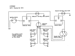

Rescued attachment 170902_wiring_diagram.jpg

Im after a really, really simple indicator/hazard diagram. Iv done a search but cant find anything.
Also, how have you all joined the wires for all three indicators (assuming they all need to be joined together)?
how about this -


Rescued attachment 170902_wiring_diagram.jpg
Thanks whippy. Why is the relay before the indicator switch? Shouldnt the switch operate the relay?
quote:
Originally posted by speedyxjs
Thanks whippy. Why is the relay before the indicator switch? Shouldnt the switch operate the relay?
quote:
Originally posted by Mr Whippy
quote:
Originally posted by speedyxjs
Thanks whippy. Why is the relay before the indicator switch? Shouldnt the switch operate the relay?
the relay doesn't know where it is in the circuit and putting it infront of the selector switch means you don't need one per side. Think of the switch as just earthling the relay and allowing it to operate
[Edited on 30/10/09 by Mr Whippy]

note though that if you use indicator relays that at use bi-metal contacts then the flash rate for the hazards will be twice as long as the indicator
as its now powering 4 lamps not 2. So its best to use the microchip timer ones for LED's that their flash rate doesn't change with current
flow.
[Edited on 30/10/09 by Mr Whippy]