mark chandler
|
| posted on 19/4/08 at 10:33 AM |

|
|
Got my JAW working
Hi all
In the spirit of Locost I purchased a JAW controller and wideband Lambda sensor a few weeks ago, the JAW arrived in the week so soldered up.
I declined the display on the basis that this is just a 5v voltmeter so ran it all up on the table just now and all looks good.
As the sensor heats you see the displays changing, using my £4 voltmeter I get a clear reading of the AFR, this will be piped into my megasquirt for
logging but with two outputs on the JAW I can monitor when driving if required.
Now all I need is a better day to start mapping my car, its cold and horrible down south today.
Costs are:
Lambda Bosch LS012 ebay BIN £30
JAW shipped $46 so ~ £26
Lambda bung for exhaust £5
Its all looking very promising.
Here's a shot of the display running in free air.
 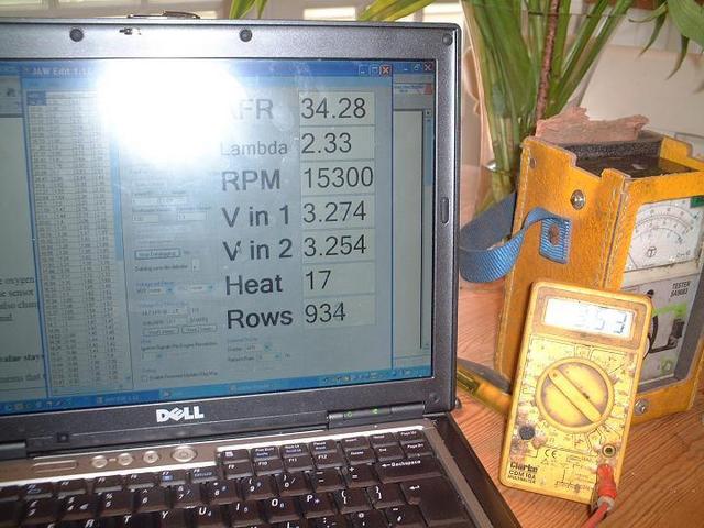
Rescued attachment Jaw_screen_shot_small.JPG
|
|
|
|
|
lsdweb
|
| posted on 19/4/08 at 10:57 AM |
|
|
Half the price of an Innovate LC1 (I paid £125 for mine) - I just wish I could solder properly!
|
|
|
coozer
|
| posted on 19/4/08 at 11:35 AM |
|
|
Wish I could understand all this electronic trickery pokery
I WANT ONE!
1972 V8 Jago
1980 Z750
|
|
|
mark chandler
|
| posted on 19/4/08 at 11:40 AM |
|
|
I have not connected to my megasquirt yet, but you have a table you can edit which sets up the AFR to Vout, this is seperate for both outputs so you
could emulate an Innovate easily enough and buy a cheap voltmeter for a dash display
Best thing to do is download the application and have a looksee, it kicks off without the JAW being connected.
It also has a datalogging facility for you carb chaps, just provide an RPM signal, this is held locally and downloads as a CSV extract so you do not
need your laptop onboard to see and capture whats going on.
Infact the more I play with it the better it gets.
Soldering is also a doddle, I could not read the resistor values so just used a multimeter, only a few parts so took an hour to complete.
[Edited on 19/4/08 by mark chandler]
|
|
|
blue2cv
|
| posted on 19/4/08 at 04:52 PM |
|
|
Still waiting for my kit to arrive
|
|
|
mark chandler
|
| posted on 19/4/08 at 05:31 PM |
|
|
FYI, From PP order to arrival was around 20 days for me.
|
|
|
David Jenkins
|
| posted on 19/4/08 at 06:02 PM |
|
|
Put my order in a couple of days ago.
One task I see is to improve the config software so it fits on my crummy old laptop... 
|
|
|
paulf
|
| posted on 19/4/08 at 06:18 PM |
|
|
It has a setting for LC1 compatability or you can load any config you require.
I have obtained one also and hope to try it out early next week ,I am going to need to make a case for it before I can install it permanently in the
car.
Paul.
quote:
Originally posted by mark chandler
I have not connected to my megasquirt yet, but you have a table you can edit which sets up the AFR to Vout, this is seperate for both outputs so you
could emulate an Innovate easily enough and buy a cheap voltmeter for a dash display
Best thing to do is download the application and have a looksee, it kicks off without the JAW being connected.
It also has a datalogging facility for you carb chaps, just provide an RPM signal, this is held locally and downloads as a CSV extract so you do not
need your laptop onboard to see and capture whats going on.
Infact the more I play with it the better it gets.
Soldering is also a doddle, I could not read the resistor values so just used a multimeter, only a few parts so took an hour to complete.
[Edited on 19/4/08 by mark chandler]
|
|
|
David Jenkins
|
| posted on 20/4/08 at 08:34 AM |
|
|
Trouble is, most of that forum's been trashed by spam. I don't think the site owner has the skills to block it (he has called for help
from anyone who can).
UPDATE!
I just had a look - someone's had a clear-out, so maybe the spam problem's been addressed.
[Edited on 20/4/08 by David Jenkins]
|
|
|
David Jenkins
|
| posted on 20/4/08 at 10:44 AM |
|
|
quote:
Originally posted by robocog
Ordered my sensor as well yesterday, hopefully the right one (LSU 4.2)@£35 I'm as excited as an excited thing
If it's the same one as I got off ebay (0 258 006 066) stand by to be a little confused! It's 5-wire to the sensor, where the JAW unit
talks about 6-wire. In fact it's 6-wire to the plug and 5-wire to the sensor, as there's a potentiometer in the plug unit.
I haven't yet worked out how to deal with that, but the sensor itself is a sister to the one that's specified - just the connector is
different (allegedly).
|
|
|
David Jenkins
|
| posted on 20/4/08 at 12:03 PM |
|
|
Unsure - watch this space!
|
|
|
paulf
|
| posted on 20/4/08 at 12:19 PM |
|
|
The 6th wire goes to the plug and connects to the calibration resistor built into the sensor plug.As long as the coulors are matched it will be
correct,I have a couple of Nissan sensors which are LU4.2 s but with a rectangular conector and will be experimenting with them.
Paul.
|
|
|
mark chandler
|
| posted on 20/4/08 at 01:39 PM |
|
|
The one with the wires in a row is the sensor I used, do not worry about the connections as they are 1 - 1 through the plug, the 6th one has something
internal, to do with free air calibration so you just match colours, green being the missing one.
The kit came with some crimps for the plug, the plastic heads on these are to large, you need to cut off the plastic shields, solder on the wire then
put some shrink warp over the top as insulation.
I used a short bit of trailer board wire as this has all the colours you need + one spare.
Regards Mark
|
|
|
mark chandler
|
| posted on 20/4/08 at 02:18 PM |
|
|
Thinking about adding a display now so Ebay will spring me a nice panel mounted 20v DC meter, take the 5v source power from board and away I go.
This should give me a good dash mountable solution for £7 so cheaper than the JAW display.
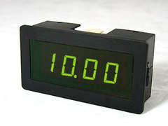 
Rescued attachment LED display.jpg
|
|
|
paulf
|
| posted on 20/4/08 at 07:48 PM |
|
|
Will you connect it to the second ouput and configure it in volts or to the original display connector? I cant find a circuit diagram for the JAW so
dont know how the original is configured.
I saw some similiar displays on ebay but will a 20v one have the correct reolution to read 0 - 5v as it needs to be a 3 digit resolution? ie 14.7 afr
needs to read 1.47 volts 20- 1 2.00 volts and 10- 1 1.00 volts
Paul
quote:
Originally posted by mark chandler
Thinking about adding a display now so Ebay will spring me a nice panel mounted 20v DC meter, take the 5v source power from board and away I go.
This should give me a good dash mountable solution for £7 so cheaper than the JAW display.
[Edited on 20/4/08 by paulf]
|
|
|
paulf
|
| posted on 21/4/08 at 03:25 PM |
|
|
I have got mine working today, was a bit confused at first as the screen readings didnt change but could read the calibration value etc and write
settings to unit .Eventually realised that the display on right half of screen doesnt work until you click the datalog button.Then tried it with a
blowlamp as a fuel source and all works ok.
Best bit is it works with the 2 sensors I bought off Ebay some time back for £5 each brand new.
Just need to work out how to put it in a case and keep the voltage regulator for the sensor heater cool, as it gets very hot at present, i may remove
it from the board and attach with flying leads to allow me to mount it on the case.
Paul.
|
|
|
David Jenkins
|
| posted on 21/4/08 at 03:43 PM |
|
|
It's amazing just how hot a voltage regulator can get, even when it's running well within the limits.
I think that I'll put my unit in a metal case I've got, and use a small fan to blow some air across the heatsink. I think Maplins sell a
small 12v fan that'll do the trick.
|
|
|
mark chandler
|
| posted on 21/4/08 at 08:34 PM |
|
|
The LM 317 regulator puts out 5v at 1.5 amps so pinching a few milli amps to power the display should not cause an issue. As above once the sensor is
hot on a running engine the heat should fall away from the regulator as the load drops right away.
I need to have a measure up on my megasquirt case as I may combine into one package, small PC fan and move the regulator on to the case may be the
easy option.
In answer to the other question, you get two 5v out's on the board, you can map the afr across these independantly so I can emulate an LC1 for
megasquirt and punt something else for the display.
As the numbers to be on the display will be meaningless I can set 2.5v as correct mixture and have a sliding scale either side to cover the whole
range, need to have a play.
Roll on the weekend, ebay purchase on the display just now and china shipping usually beats UK suppliers in my experience.
This is the chap I ended up with, 0 - 20v as its powered
linkthe unpowered ones run 7-20v
[Edited on 21/4/08 by mark chandler]
|
|
|
MikeRJ
|
| posted on 22/4/08 at 10:14 AM |
|
|
quote:
Originally posted by David Jenkins
It's amazing just how hot a voltage regulator can get, even when it's running well within the limits.
If it gets that hot it probably isn't running within it's limits, or is marginal. People very often just see the maximum current
capability of a regulator and don't consider power dissipation which is a separate issue.
|
|
|
David Jenkins
|
| posted on 22/4/08 at 11:00 AM |
|
|
quote:
Originally posted by MikeRJ
quote:
Originally posted by David Jenkins
It's amazing just how hot a voltage regulator can get, even when it's running well within the limits.
If it gets that hot it probably isn't running within it's limits, or is marginal. People very often just see the maximum current
capability of a regulator and don't consider power dissipation which is a separate issue.
OK - maybe I should have said "warm" not "hot"!
I have found that a regulator like this one can get very warm to the touch - but it shouldn't get so hot that it burns you. Maybe I'll
fit a more generous heatsink when my kit arrives...
I do plan to fit a fan to help with the cooling.
|
|
|
David Jenkins
|
| posted on 22/4/08 at 01:01 PM |
|
|
Anyone know of a good source for a connector for the 6066 sensor?
The only place that came up in Google was this one.. The price wasn't bad, even including
postage, but trying to place an order was dreadful! I would have to prove who I am before they would accept an order for a total of Au$15 - around £4
or £5! Proving my identity could be done in various ways, such as sending a photocopy of my driving licence, letting them interrogate PayPal for my
verified address (a legit way, I hasten to add) and various other intrusive methods. I decided to leave them alone.
What a bunch of...<insert favourite word>!
|
|
|
paulf
|
| posted on 22/4/08 at 09:10 PM |
|
|
I also need to find a source of connectors for mine, my sensor is a nissan fitment and has a rectangular connector.I have been looking for ages but
not found a supplier, but do now have a bosch part number so need to find a good bosch auto electrician, i asked in a local place with no success.I
suspect mine is also used on GM vechiles and is the sensor type used with the AEM wideband.
Paul.
Paul
|
|
|
mark chandler
|
| posted on 22/4/08 at 10:01 PM |
|
|
The JAW supplied crimps do work as long as you lose the plastic tops, I did consider cutting away the shroud exposing the pins then just soldering on
wires. If the crimps had failed this was option 2 for me. When done its all burried in gaffer tap anyway. I would worry about spending the extra if
you fail on the supplied stuff.
An alternative is just to use thicker wire, force a tack or small nail inside the insulator to stretch it then just push the whole wire down over the
pin.
|
|
|
paulf
|
| posted on 23/4/08 at 09:50 AM |
|
|
I have connected mine using the supplied crimps with the insulator cut off also, it does work but the correct connector would be nice.I had considered
using the crimps and then filling the space between them with potting compound or epoxy resin.
Paul.
quote:
Originally posted by mark chandler
The JAW supplied crimps do work as long as you lose the plastic tops, I did consider cutting away the shroud exposing the pins then just soldering on
wires. If the crimps had failed this was option 2 for me. When done its all burried in gaffer tap anyway. I would worry about spending the extra if
you fail on the supplied stuff.
An alternative is just to use thicker wire, force a tack or small nail inside the insulator to stretch it then just push the whole wire down over the
pin.
|
|
|
David Jenkins
|
| posted on 28/4/08 at 02:43 PM |
|
|
I placed an order with them in the end!
Not quite as bad as I thought it would be, mostly because I used PayPal. This meant that they could verify my address without faffing around.
I'll let you know how long it takes, and how good the product is, when it arrives.
quote:
Originally posted by David Jenkins
Anyone know of a good source for a connector for the 6066 sensor?
The only place that came up in Google was this one.. The price wasn't bad, even including
postage, but trying to place an order was dreadful! I would have to prove who I am before they would accept an order for a total of Au$15 - around £4
or £5! Proving my identity could be done in various ways, such as sending a photocopy of my driving licence, letting them interrogate PayPal for my
verified address (a legit way, I hasten to add) and various other intrusive methods. I decided to leave them alone.
What a bunch of...<insert favourite word>!
|
|
|


.jpg)

