Chippy
|
| posted on 16/9/07 at 05:09 PM |

|
|
MS Question re. trigger wheel settings.
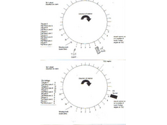
Hi all, question for the knowledgable on MS. In the attached picture, (large in my photo album, under MS installation), the trigger wheel setting at
the bottom is as shown in the MS set up details. The top one is how my engine, (cossie V6), is set up, which would be a mega job to change, as the
toothed wheel is cast and keyed to the crank. What I want to know is what would the settings be for 6cyl spread sheet along side my set up, and is it
even possable to set it up correctly? Cheers Ray
 
Trigger wheel small
|
|
|
|
|
matt_claydon
|
| posted on 16/9/07 at 05:36 PM |

|
|
Not sure what you mean by 'TDC Here' in your diagram. The diagram should be drawn with the engine at TDC position - no particular tooth
'lines up with TDC', it's just a matter of which tooth the VR sensor is over when the engine is in that position.
There is another key number you have not considered in your diagram - the 'trigger angle'. In the example this would have been 60 degrees,
as tooth 3 (trigger A) passes the sensor 60 degrees before cylinder 1 is at TDC. In theory you could put tooth 1 as trigger A and a trigger angle of
40 degrees. However, I think there are restrictions on what angles you can use so you may have to use an 'earlier' tooth and a larger
angle.
Clear as mud I expect 
[Edited on 16/9/07 by matt_claydon]
|
|
|
Chippy
|
| posted on 16/9/07 at 09:29 PM |

|
|
Hi Matt, the TDC position is where, when the engine is at TDC, the timing pin lines up with that tooth, "ie" tooth 1, so basicaly what you
see on the drawing is how the thing looks when at TDC. The part that worries me is that the "Missing tooth" comes , as I see it, within
the first 60deg section. I worked it out that "Trig pos A" would start at tooth 35, with "Trig rtn pos A" being at tooth 4,
and so on, but will that work? Cheers Ray
|
|
|
matt_claydon
|
| posted on 17/9/07 at 07:47 AM |

|
|
Just had a look at the documentation and it seems like you should be fine with tooth 35 as trigger A and a trigger angle of 60 deg. Trigger B would be
tooth 11 and trigger C would be tooth 23.
This assumes you will be using wasted spark. If using individual coils for each plug then you will need six triggers and you would then have:
A 35
B 5
C 11
D 17
E 23
F 29
|
|
|
Chippy
|
| posted on 17/9/07 at 12:17 PM |

|
|
Hi Matt, thanks mate, that is how I worked it out, the only thing that I was worried about was that the missing tooth came within the first 60deg
sector. Cheers Ray
|
|
|


