piddy
|
| posted on 15/1/07 at 05:13 PM |

|
|
Configuring mega to use LC-1
I've been following This to configure my Mega squirt to use a LC-1.
In the part where it says Lastly (and only for MS-II users, MS-I can skip this) you’ll want to go to TOOLS>Calibrate AFR Table and choose the
Innovate 10-20:1 0-5v setting and click OK, this will calibrate the MS to read the LC-1 properly.
I don't have the option in tools (Or does the LC-1 And Maga squirt all have to be powered up in the car)?
I've taken a look at my AFR table and it reads 11.5 on all rev ranges below 60kpa and 19.5 & 18.5 above 60kpa.
This cant be correct can it?
|
|
|
|
|
piddy
|
| posted on 15/1/07 at 06:50 PM |

|
|
Mine has 37 pins.
And on the case says MSnspark extra.
both MSI and MSII being left blank.
[Edited on 15/1/07 by piddy]
|
|
|
TangoMan
|
| posted on 15/1/07 at 08:48 PM |

|
|
If it's MSnS then it must be MS1.
I have just looked at my software and I don't have that option either. Maybe it needs to be connected to the unit to extend the menu.
Summer's here!!!!
|
|
|
CairB
|
| posted on 15/1/07 at 09:27 PM |

|
|
Piddy,
Follow the instructions on the MS site.
For MS1 in principle:
You need to set the wb to give 0v at 10/1 and 5v at 20/1 AFR. Use the Innovate software to do this.
Then instruct the Megasquirt that you are applying a wb signal to its O2 input. This is configured in the latest version of MegaTune in Enrichments -
Exhaust Gas Oxygen - EGO Sensor Type - Set to Wide Band
Set EGO switch point to 2.35 (14.7/1)
For Megatune to interpret the signal correctly you need to set the relevant entry in the msns-extra.ini file so that it can display and log the
correct values. I believe that you can do this with the Configurator that is accessed from the File option in the latest Megatune. Set it for the
INNOVATE_0_5_LINEAR "Innovate, PLX 0-5V 10-20:1 AFR" by setting it to set and the others to unset.
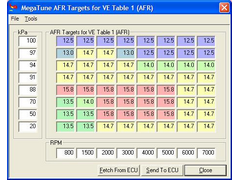
You specify the contents of the AFR table.
Here's a copy of my current one.
 
AFR Table
You should then be able to see the AFR displayed in Megatune when you run the engine and be able to datalog the values.
If you want to enable AFR table values where the MS will try to correct to the values you specify in the table.
I use an older version of Megatune, but I believe that the principles are similar.
The 37 pins you refer to will be the pins on the D type connector I presume. The pins that Mark was referring to are on the microcontroller inside.
If your using ITB's and Speed Density algorithm then I suggest that you spread your MAP values with about 2kpa intervals from 90 - 100kp. This is
because the fueling approximately doubles from 90 -100.
I, and others, have found that Alpha-n algorithm gives best full load performance when using ITB's. I have posted on this previously on both here
and MS.
HTH
Cheers,
Colin
[Edited on 15/1/07 by CairB]
|
|
|
piddy
|
| posted on 16/1/07 at 08:32 PM |

|
|
Thanks for you help and advise.
One thing.
How do you do this please.
quote:
If your using ITB's and Speed Density algorithm then I suggest that you spread your MAP values with about 2kpa intervals from 90 - 100kp. This
is because the fueling approximately doubles from 90 -100
|
|
|
CairB
|
| posted on 16/1/07 at 09:24 PM |

|
|
You can edit the values for MAP & RPM in the VE table.
The MS software then performs linear interpolation to determine the VE which is the main variable for your injector pulse width.
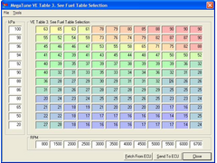
Here is a work in progress MAP based VE table. I need to extend the RPM range after my recent mods 
 
SD MAP VE Table
Ignore that it says its table 3 as I have a dual table mode implemented.
The VE values for your engine will be different - its only an example.
If you look at how the VE changes with respect to MAP for a given RPM you will see that it is non linear around the 90kpa region.
If you don't set the MAP increments small around this region then you tend to miss this which then results in undesirable AFR's.
Having said all that you will be able to get running with a table with evenly spread values.
It's just that you probably won't get the best out of it.
This steep rise in VE above 90kpa seems to be a phenomenon with ITB's.
I believe most of the performance ECU's do not use speed density algorithm but Alpha_n.
I use a mixture of both.
Cheers,
Colin
|
|
|
piddy
|
| posted on 17/1/07 at 03:04 PM |

|
|
Cheers for that.
Martin.
|
|
|


