rjbrookes
|
| posted on 14/7/06 at 09:14 PM |

|
|
Please Explain the Balance Bar Adjustor
Hi,
Just want to make sure i am doing the correct thing before i start messing about with the brakes.
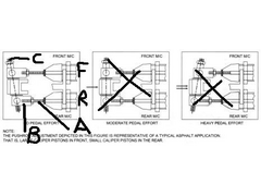
Hopefully a picture attached of a Balance bar.
I keep locking the one front wheel, so i am tinkering with the supension as to balance the weight - i think i have got the idea of this one now. They
seem to brake more evenly and better after a little play earlier.
From the pic, F = Front, and B = back. Which bit do i have to move to adjust the balance. Do i screw A further in and out of B, or do i have to
screw B further up and down C???
If someone could explain the effects of moving either A, B or C that would be great!
Thanks
Russ
 
Rescued attachment bb1.jpg
|
|
|
|
|
another_dom
|
| posted on 14/7/06 at 09:37 PM |

|
|
Russ,
OK - first you adjust pushrod lengths (A) to ensure full range of motion of the master cylinders. You then need to have clearance between the pushrod
clevis' (B) and the spherical welded into the brake pedal (approx 1/8" total, just ensure it isn't binding at full adjustment).
Rotating C will then vary the brake balance. The Wilwood site (www.wilwood.com) is very good for technical information on braking systems.
Dom.
|
|
|


