Guinness
|
| posted on 20/9/07 at 09:42 AM |

|
|
Another Dom
Hi Dom
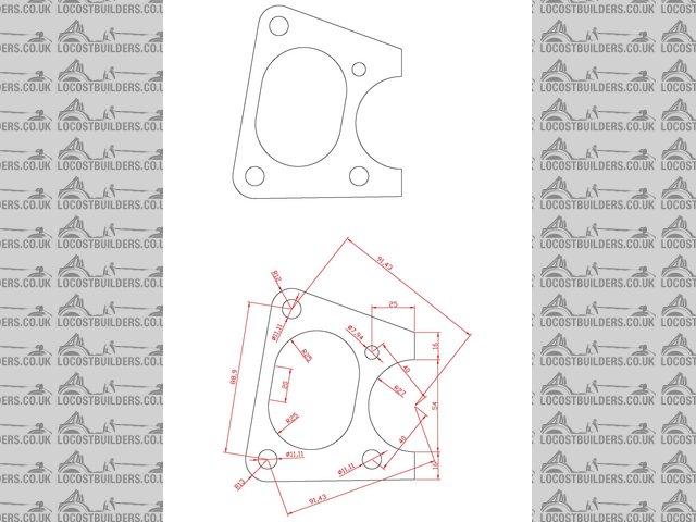
Please find attached a sketch as per your fax. Hope it's OK. Couldn't really understand why the left side was at an angle / couldn't
work out what it should be. Also is the top hole on the hub mount supposed to be smaller than the bottom one? On your sketch it is 5/16" when
the other three are 7/16"?
Cheers
Mike
P.S. Sorry it's big!
[img][/img]
|
|
|
|
|
another_dom
|
| posted on 20/9/07 at 09:49 AM |
|
|
Mike,
That is big! The top hole is supposed to be 5/16, as you have drawn it. The left side does need to be at an angle though! The bottom left 7/16
mounting hole needs to be in line with the bottom right 7/16 mounting hole. The top left 7/16 mounting hole needs to be 3.5 inches from the bottom
left, and a line drawn between the two left hand mounting holes needs to 79.9mm from the centre of the hub. Does that make sense? I can work out the
angles using trig but hoped CAD might allow for some automated calculations?
Very quick turnaround - very impressed!
Dom.
|
|
|
Guinness
|
| posted on 20/9/07 at 10:01 AM |
|
|
Ok Dom, I can see what you are after, but I'm afraid it's beyond my ability on CAD to work out what the angle should be!
Mike
|
|
|
another_dom
|
| posted on 20/9/07 at 10:04 AM |
|
|
Oh dear, I'll have to do it the old fashioned way! Give me a while to crunch the figures and I'll provide the locations as cartesian
dimensions.
Cheers,
Dom.
|
|
|
another_dom
|
| posted on 20/9/07 at 10:55 AM |
|
|
This is proving a little more complicated than I had hoped!
The two left hand mounting points are on a 91.432 mm radius from the centrepoint of the hub. Is it possible to place the bottom left mounting point
on this radius, and in line with the bottom right mounting point? If not I make the dimensions 85.935 'left' and 31.225 mm
'down' from the hub centre point. Is it then possible to place the top left mounting point on the same radius, with a 3.5 inch linear
distance between the two left hand mounting points? I hope so!
Dom.
[Edited on 20/9/07 by another_dom]
|
|
|
another_dom
|
| posted on 20/9/07 at 11:22 AM |
|
|
Finished my number crunching Mike,
Top left mounting point centre will be 71.845 mm 'left' and 56.551 mm 'above' the hub centre point. That will position all of
the mounting points accurately.
Thank you,
Dom
|
|
|
Guinness
|
| posted on 20/9/07 at 11:31 AM |
|
|
Why didn't you say so in the first place 
Done!
Another Dom 2
Let me know how this looks.
Cheers
Mike
|
|
|
mcerd1
|
| posted on 20/9/07 at 12:04 PM |
|
|
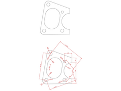
don't mean to butt in - but here's one I did 
(I worked out the angles with CAD)

Have I got it right ? do I win a prize
[Edited on 20/9/07 by mcerd1]
|
|
|
another_dom
|
| posted on 20/9/07 at 12:52 PM |
|
|
Brilliant,
Thanks very much both! Mike, final titivation ... is it possible for the bottom edge to be perpendicular to the right hand edge? I suspect the
radius on the bottom left will have to change.
I have to say I'm impressed. All I need to do now is get them cut to the same accuracy they've been designed and arrange a contribution
to the beer/brew/kit fund.
Dom.
|
|
|
another_dom
|
| posted on 20/9/07 at 12:57 PM |
|
|
Mcerd1 (sorry can't find your name in your last few posts!)
I was confident it could be done in CAD, and it looks like we've got the same result! You would have won a prize if you hadn't omitted
the oval hole. 9/10
|
|
|
another_dom
|
| posted on 20/9/07 at 01:02 PM |
|
|
Should also add that anyone building a Malone ST/F1000 (Skunk), and using Wilwood NDL calipers with 3.5 inch mounting centres on the new 12 inch
diameter discs is welcome to add their brackets to my order.
It has to be said I'm not expecting a mad rush!
Dom
[Edited on 20/9/07 by another_dom]
|
|
|
mcerd1
|
| posted on 20/9/07 at 01:25 PM |
|
|
quote:
Originally posted by another_dom
... is it possible for the bottom edge to be perpendicular to the right hand edge? I suspect the radius on the bottom left will have to
change.
to make the bottom edge perp. to the right edge and keep the 16mm dim. - the bottom left radius would have to be 11.775mm
if you made that bottom left radius 11.775mm would you keep the top left one at 13mm ??
I would have added the big slotted hole - but there are no dims. in the above to possition it
this is all good practice for me (I've got my own Wilwood caliper brakets to design later - Midilights on Sierra uprights - to suit granada
discs)
-Robert
|
|
|
another_dom
|
| posted on 20/9/07 at 01:29 PM |
|
|
This is hardly fair on you Robert as you missed the initial fax!
The only critical dimensions are the locations and diameters of the mounting holes with respect to the hub. The outer edge and the oval hole were
placed by me to look about right (who needs finite element analysis)!
In all honesty, my preference for a nice right angle between the base and right hand edges is my OCD manifesting itself again; it will have absolutely
no impact on the function of the component.
Dom.
|
|
|
another_dom
|
| posted on 20/9/07 at 01:49 PM |
|
|
Just noticed Mike has already changed the top left radius to 12 mm so an 11.775 (or thereabouts!) bottom left radius works well.
Can it be done? I've been putting this job off for a very long time. I keep downloading CAD packages and singularly failig to get to grips
with them!
Dom.
[Edited on 20/9/07 by another_dom]
|
|
|
mcerd1
|
| posted on 20/9/07 at 02:05 PM |
|
|
How about this then

btw - I can send you this in most CAD formats (*.dwg, *.dxf, *.3dm *.sat, *.stl, etc....)
I might even manage to get it into a file DSTV (used in lots of CNC machines)
|
|
|
another_dom
|
| posted on 20/9/07 at 02:15 PM |
|
|
Getting dangerously close now, but I don't really like the bulge in the bottom left corner. I would rather adjust the radius on the corners to
suit (maintaining around 7-8 mm of material around the mounting points), or worst case extend the lower right hand edge down to meet a line extended
from the bottom left radius.
Then it'll be lovely (It'll be hidden behind the wheel and caliper admittedly, but I'll know its there)!
Dom.
[Edited on 20/9/07 by another_dom]
|
|
|
mcerd1
|
| posted on 20/9/07 at 03:00 PM |
|
|
how about this time?


make a new text file and copy and paste the following into it:
quote:
ST
** F1.nc1
123456
1
F1
F1
S275
1
PLT10*97
B
111.27
97.61
10.00
10.00
10.00
0.00
78.500
3.186
0.000
0.000
0.000
0.000
AK
v 11.68u 0.00 0.00 0.00 0.00 0.00 0.00
97.61 0.00 0.00 0.00 0.00 0.00 0.00
-395.90 59.17t 0.00 0.00 0.00 0.00 0.00
97.61 16.00 -27.00 0.00 0.00 0.00 0.00
88.38 68.37 -27.00 0.00 0.00 0.00 0.00
97.61 72.68t -27.00 0.00 0.00 0.00 0.00
97.61 70.00 0.00 0.00 0.00 0.00 0.00
97.61 86.00 0.00 0.00 0.00 0.00 0.00
29.79 110.62 11.78 0.00 0.00 0.00 0.00
16.40 115.48t 11.78 0.00 0.00 0.00 0.00
14.14 101.41 0.00 0.00 0.00 0.00 0.00
0.05 13.65 11.78 0.00 0.00 0.00 0.00
11.68 0.00 0.00 0.00 0.00 0.00 0.00
IK
v 141619.50u 882331.51t 11.78 0.00 0.00 0.00 0.00
12.42 46.54 0.00 0.00 0.00 0.00 0.00
15.59 66.29 -25.00 0.00 0.00 0.00 0.00
64.96 58.37 0.00 0.00 0.00 0.00 0.00
61.79 38.62 -25.00 0.00 0.00 0.00 0.00
141619.50 882331.51 0.00 0.00 0.00 0.00 0.00
BO
v 11.68u 11.77 11.11
v 25.76u 99.55 11.11
v 72.61u 11.77 11.11
v 72.61u 74.22 7.94
EN
save this with the file name 'F1'
then change the file type to a *.nc1 and you have a DSTV file for CNC (it should work :? )
if you need *.dwg or *.dxf instead I can e-mail you them
-robert
[Edited on 20/9/07 by mcerd1]
|
|
|
another_dom
|
| posted on 20/9/07 at 03:13 PM |
|
|
Top work Robert, and thanks also to Mike for his help with this one. The shop down the road requested .dxf so I will PM you my email if I may.
Now I don't suppose anyone fancies doing my wiring? Only joking.
Dom.
|
|
|
mcerd1
|
| posted on 20/9/07 at 03:22 PM |
|
|
No problem - I can send you a dxf (AutoCAD 2000 format with no dimensions I assume ? )
btw - I assumed 10mm thick plate in the above, won't matter in a 2D dxf though
sorry mike, I seem to have taken over, hope you don't mind 
Also - if anyone wants to know how I worked out the angles in CAD (or has any other drafting problems) I'm happy to help as much as I can
-robert
[Edited on 20/9/07 by mcerd1]
|
|
|
NeilP
|
| posted on 20/9/07 at 05:15 PM |
|
|
quote:
Originally posted by another_dom
...but I don't really like the bulge in the bottom left corner...
Angle grinder?....
If you pay peanuts...
Mentale, yar? Yar, mentale!
Drive it like you stole it!
|
|
|