Delinquent
|
| posted on 16/10/07 at 08:11 PM |

|
|
Track Rod end position
Just want to check something I'm not 100% sure on.
My steering rack length and position is being tailored to fit exactly in line with the inboard pivot of the upper wishbone. I've worked out what
Ackerman I want, and the length of the steering arm needed for the lock required from the rack.
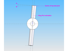
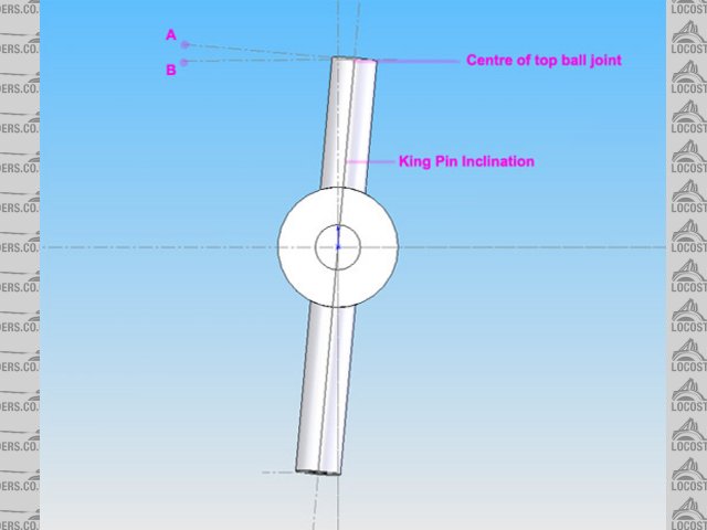
Attached is a very quick diagram to try and show my problem. A is centre of the ball joint when measured perpendicular to the KPI, B is the centre of
the ball joint when measured parallel to the floor.
where should it be - A or B?!
[Edited on 16/10/07 by Delinquent]
[Edited on 16/10/07 by Delinquent]
Rescued attachment steering.jpg
|
|
|
|
|
daviep
|
| posted on 16/10/07 at 11:23 PM |
|
|
I'm ready to be shot down and probably rightly so
I say B
If the inboard pivot of your rack is the same height as the inboard pivot of the wishbone, then then the pivot of the TRE should be the same height as
the outer ball joint.
If you drew it looking from the front it would look clearer (at least to me) I think.
Davie
|
|
|
t.j.
|
| posted on 17/10/07 at 06:12 AM |
|
|
looking at the picture I would say it's caster you have drawn.
But if it is KPI/Camber I would like to know why the angle is needed.
IMO only the point is important and not the angle.
The angle of the wichbones tru the points off the balljoint and bracket are needed.
Maybe i'm wrong, never to old too learn
[Edited on 17/10/07 by t.j.]
Please feel free to correct my bad English, i'm still learning. Your Dutch is awfull! :-)
|
|
|
Delinquent
|
| posted on 17/10/07 at 08:10 AM |
|
|
quote:
Originally posted by t.j.
looking at the picture I would say it's caster you have drawn.
But if it is KPI/Camber I would like to know why the angle is needed.
IMO only the point is important and not the angle.
The angle of the wichbones tru the points off the balljoint and bracket are needed.
Maybe i'm wrong, never to old too learn
[Edited on 17/10/07 by t.j.]
Sorry, long day yesterday. It should have said "King Pin Axis" rather than Inclination - so the combination of both castor and camber
together.
My confusion is from the piece I read up to check this, which said that with the inboard pivot being on the axis through the centreline of the upper
wishbone, the TRE should be located through the axis of the outboard pivot of the upper wishbone - the terminology made me think that the
"axis" through the outboard would be perpendicular to the King Pin Axis rather than parallel to the floor.
|
|
|
britishtrident
|
| posted on 17/10/07 at 12:28 PM |
|
|
Conventional Ackerman geometry only works on steering setups with a centre track; eg a steering box and idler arm dosen't work with rack &
pinion steering.
As been covered many times in the forum to get toe-out in turns the steering rack centre has to be moved rearwards of an imaginary line joining the
outer track rod end ball joints.
[I] What use our work, Bennet, if we cannot care for those we love? .
― From BBC TV/Amazon's Ripper Street.
[/I]
|
|
|
britishtrident
|
| posted on 17/10/07 at 12:36 PM |
|
|
Also forget about making the inner track balls in line with wishbone pivots, it doesn't work that way because if the steering arm is bent/angled
to provide Ackerman or clearance it throws it out, what is critical is the length of the steering track rods is correct for the vertical position
of the rack centre line and track end centre.
[Edited on 17/10/07 by britishtrident]
[I] What use our work, Bennet, if we cannot care for those we love? .
― From BBC TV/Amazon's Ripper Street.
[/I]
|
|
|
Delinquent
|
| posted on 17/10/07 at 01:02 PM |
|
|
quote:
Originally posted by britishtrident
Also forget about making the inner track balls in line with wishbone pivots, it doesn't work that way because if the steering arm is bent/angled
to provide Ackerman or clearance it throws it out, what is critical is the length of the steering track rods is correct for the vertical position
of the rack centre line and track end centre.
[Edited on 17/10/07 by britishtrident]
The rack has been positioned in line with the upper wishbone pivots because I can get a straight path to the steering arms - the upper wishbones are
basically a right angle triangle trailing the axle line, so that side is all fine. The ackerman is set as negative, the convergence point lies 3/4 the
wheelbase behind the rear axle line which according to my diagram gives the correct toe without having to move the rack backwards, unless I'm
missing something.
The problem is I don't know which is the correct vertical position - hence to diagram above - do I calculate the height relative to the King Pin
Axis (which would put it at "A" or parallel to the floor, which would put it at "B"
|
|
|
Doug68
|
| posted on 17/10/07 at 02:39 PM |
|
|
Get yourself a copy of this if you want to do the job properly.
If you look at the picture below you can see the steering rack length etc are far from what would appear as theoretically ideal.
However the analyzed bump steer is only a fraction of a mm over the entire range of movement of the suspension.
Or to put it another way I think with the use of proper analysis tools to make the most of off the shelf components a bunch of cash can be saved in
avoiding having to fab custom uprights, racks etc to achieve the same effect.
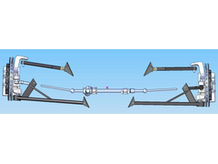 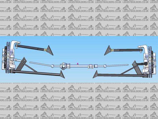
Rescued attachment Untitled-2.jpg
Doug. 1TG
Sports Car Builders WA
|
|
|
Delinquent
|
| posted on 17/10/07 at 03:18 PM |
|
|
I was warned against that program by a pro - though I must admit it's chances of being any worse than me using bits of string and rulers with
pins in......
Can I ask what uprights you've got there? I'd pretty much resigned myself to having them made but still on the lookout. R&P is
definitely going to be a Titan unit but obviously having my own uprights machined is going to be pricey.
|
|
|
Doug68
|
| posted on 17/10/07 at 03:27 PM |
|
|
I'd be interested to know why your pro doesn't like Susprog, as it seems to be quite widely used as far as I can see Lotus Eng. and others
have also developed this type of app but at far higher costs.
The results of Susprog I have also verified in my 3D model, so I know if I build the thing properly to the design I will get the same results.
The uprights I'm using are Corvette C5 units. Which can be had from eBay in the USA for ~US$100 each.
Doug. 1TG
Sports Car Builders WA
|
|
|
Delinquent
|
| posted on 17/10/07 at 03:31 PM |
|
|
ahhh the C5's - several people have mentioned those to me, I've been a bit lazy though, keep on intending to try and find one to get all
the dims off to check against my "decisions" made. Might be worth a punt at the money.
Do you know what the various built in angles are on it?
To be honest I don't know enough about it all to really understand his dislike of them, (and not having used them took his comments at face
value) but I'll certainly ask him to expand on it a bit for you.
|
|
|
britishtrident
|
| posted on 17/10/07 at 08:48 PM |
|
|
Convergence point just dosen't hold true with rack and pinion steering, it gets wiped out by the greater effect of conflict of the arcs of the
steering arms and track rods, work from first principles plot it out in plan view.
[Edited on 17/10/07 by britishtrident]
[I] What use our work, Bennet, if we cannot care for those we love? .
― From BBC TV/Amazon's Ripper Street.
[/I]
|
|
|
Delinquent
|
| posted on 17/10/07 at 10:32 PM |
|
|
quote:
Originally posted by britishtrident
Convergence point just dosen't hold true with rack and pinion steering, it gets wiped out by the greater effect of conflict of the arcs of the
steering arms and track rods, work from first principles plot it out in plan view.
[Edited on 17/10/07 by britishtrident]
Forgive me, I'm not trying to be argumentative here, just a bit confused as in all the reading I've done to get this far I've not
once seen this mentioned.
Moving the convergence point backwards or forwards I can get the toe change as little or as great as I want, so where is the difference between that
and moving the rack backwards and forwards? I've seen mention of moving the rack when you can't change the steering arm angle (effectively
can't move the convergence point) but only then?
Bit confused.
|
|
|
britishtrident
|
| posted on 18/10/07 at 07:22 AM |
|
|
Because with a rack & pinnion you can't have classic ackerman geometry the conflict of arcs will either nullify it or magnify it it. --- if
you do a plot it is fairly obvious.
In any event if the steering arms are mounted in ahead of the virtual king ping for classic ackerman you need to put the track rod end in space
occupied by the brake disk.
Because of weight transfer the inside front tyre cannot support as great a slip angle as the outside tyre. Slip angles come into play at any speed
over 2 mph.
Use 100% ackerman an you will drag the inside front tyre at an excessive slip angle --- squealing.
A lot of US cars of the 60s and 70s used too much ackerman just study a car chase in an old episode of the Rockford files.
[Edited on 18/10/07 by britishtrident]
|
|
|
Delinquent
|
| posted on 18/10/07 at 08:51 AM |
|
|
quote:
Originally posted by britishtrident
Because with a rack & pinnion you can't have classic ackerman geometry the conflict of arcs will either nullify it or magnify it it. --- if
you do a plot it is fairly obvious.
That is what's confusing me - I have plotted identical setup overlays in CAD using R&P on one, box type for the other, both inline with the
steering arm pivot points - and the difference in Ackerman effect is a total of 0.03 degrees over 34 degrees of wheel turn - comparing the resulting
toe angles from both to the ackerman calculations in Jupes "building special vehicles" that gives me near as damn it perfect Ackerman.
quote:
Originally posted by britishtrident
In any event if the steering arms are mounted in ahead of the virtual king ping for classic ackerman you need to put the track rod end in space
occupied by the brake disk.
Now that is something quite likely - I've yet to get the "proper" hubs and discs drawn up to include in CAD, only some Audi 80 ones
which aren't the intended set, but using 100% Ackerman - there is about 3mm clearance between disc and TRE using those, I fear that may
disappear with the larger discs though it's possible I could use a different rack, and use shorter steering arms which may make that problem
disappear again - will have to wait and see on that front.
|
|
|
britishtrident
|
| posted on 18/10/07 at 08:45 PM |
|
|
Unless you are building an invalid buggy you don't want 100% ackerman. Some ackerman is required to get the car to turn in on slower speed
corners but only a %.
The reason is tyres are generating cornering force they must have slip angles. It is the slip angles that lateral cornering force.
The slip angle that can be sustained is greater on the more heavily loaded outside wheel than the lightly loaded inside.
In some racing catergories particularly in the US they use small ammounts of anti-ackerman (ie toe-in on turns).
[I] What use our work, Bennet, if we cannot care for those we love? .
― From BBC TV/Amazon's Ripper Street.
[/I]
|
|
|
britishtrident
|
| posted on 18/10/07 at 08:50 PM |
|
|
Slip angles
http://www.creativecarcontrol.co.uk/modelgrip.htm
[I] What use our work, Bennet, if we cannot care for those we love? .
― From BBC TV/Amazon's Ripper Street.
[/I]
|
|
|
Delinquent
|
| posted on 18/10/07 at 08:53 PM |
|
|
quote:
Originally posted by britishtrident
Unless you are building an invalid buggy you don't want 100% ackerman. Some ackerman is required to get the car to turn in on slower speed
corners but only a %.
The reason is tyres are generating cornering force they must have slip angles. It is the slip angles that lateral cornering force.
The slip angle that can be sustained is greater on the more heavily loaded outside wheel than the lightly loaded inside.
In some racing catergories particularly in the US they use small ammounts of anti-ackerman (ie toe-in on turns).
indeed, as I mentioned earlier I don't actually have 100% ackerman, I was just saying that I can achieve it perfectly by moving the convergence
point and hence alter the angle of the steering arms - I'm only confused as to why you say that I can't use the convergence point and
hence change the steering arm angle to increase or decrease the ackerman %age.
|
|
|
britishtrident
|
| posted on 19/10/07 at 12:45 PM |
|
|
Go out and look at some real world production car setups.
[I] What use our work, Bennet, if we cannot care for those we love? .
― From BBC TV/Amazon's Ripper Street.
[/I]
|
|
|
t.j.
|
| posted on 19/10/07 at 03:34 PM |
|
|
I only used 3D drawing to see how much bump-steer i would get.
The AVON setup is fairly good.
I used the cortina upright, Escort Mk2 steeringrack, fiat 124 lower balljoint.
So drawing is one making it as the drawing is two ;-)
Please feel free to correct my bad English, i'm still learning. Your Dutch is awfull! :-)
|
|
|