NS Dev
|
| posted on 19/12/06 at 10:12 AM |

|
|
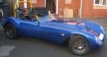
Twin bike engine chain drive countershaft arrangement
Anybody that remembers me wittling on about the countershaft arrangement for the new grasser - found a piccy on tinternet of the setup in the car that
I am basing that setup on:
(hope they don't mind me posting it! )

so you can see what I am referring to in how to mount the sprockets to the shaft and still be able to get the bearings off.
I think on this one you can't get them off.
Retro RWD is the way forward...........automotive fabrication, car restoration, sheetmetal work, engine conversion
retro car restoration and tuning
|
|
|
|
|
tks
|
| posted on 19/12/06 at 10:28 AM |
|
|
poeehhh
I told you already (like you me sometimes)
that the only way to archieve that is to make it with levels..
its sow easy!
For example start with bearing 35mm
for 20mm then the lenght to the next bearing at 38 then that bearing at 40mm
and you are there.. cant seee the problem.
will make a cad file..
i would add another bearing in that design anyway..
because else one chain is looser as the other..
Tks
The above comments are always meant to be from the above persons perspective.
|
|
|
NS Dev
|
| posted on 19/12/06 at 11:07 AM |
|
|
........how do you attach the sprockets?
Retro RWD is the way forward...........automotive fabrication, car restoration, sheetmetal work, engine conversion
retro car restoration and tuning
|
|
|
Kissy
|
| posted on 19/12/06 at 11:17 AM |
|
|
Take a look at the Gearbox Kart racing sprockets such as Kelgate:
http://www.kelgate.co.uk/info_download/Price_list_250cc.pdf
They, and Formula1, do Split-sprocket set-ups. V.Quick and plenty of ratios. May need beefing up.
|
|
|
tks
|
| posted on 19/12/06 at 11:21 AM |
|
|
on another piece of bush and then bolted throu...
The above comments are always meant to be from the above persons perspective.
|
|
|
DIY Si
|
| posted on 19/12/06 at 11:22 AM |
|
|
Could you get the shaft splined at the relevant places and maybe use either circlips or get the thing threaded too and use big nylocs/ nuts either
side perhaps? I don't know how practical this would be though, as it may cost a fortune to get made up.
Let your plans be dark and as impenetratable as night, and when you move, fall like a thunderbolt.
Sun Tzu, The Art of War
My new blog: http://spritecave.blogspot.co.uk/
|
|
|
3GEComponents
|
| posted on 19/12/06 at 11:48 AM |
|
|
The easiest way would be to use go-kart rear axle which is keyed to which you can mount a more robust version of a go-kart sprocket carrier,
i'm sure GB Engineering could help. Mount the whole thing on pillow blocks.
Or look on RS's site for power transfer components, some industrial machines use taper mounting systems for chaindrive off of some very powerful
electric motors with no ill effects, i'll find some pictures of what i mean.
Try this part number 678-237 on RS's site.
[Edited on 19/12/06 by jroberts]
|
|
|
NS Dev
|
| posted on 19/12/06 at 01:13 PM |
|
|
Ahh, had a look into using taperloc stuff.
Looked ideal, and you can buy taperloc weld flanges and taperloc sprockets and taperloc bolt flanges all at really useful pcd's, but the slip
torque ratings of all of them (apart from the really huge ones that weigh 20kg! ) are way below what the engine and gearbox will throw at them.
I guess they are seriously underquoted industrial style slip torques, but its worrying when a sensibly sized laperloc hub (1600 series or whatever the
nearest one is ) will only stand 1/4 to 1/3 of the engine/gearbox peak starting impact torque load.
Retro RWD is the way forward...........automotive fabrication, car restoration, sheetmetal work, engine conversion
retro car restoration and tuning
|
|
|
chriscook
|
| posted on 19/12/06 at 06:12 PM |
|
|
There was something on the totalkitcar website about a company that can cold form and roll splines - mainly in relation to driveshafts but they may be
able to help...
|
|
|
tks
|
| posted on 19/12/06 at 06:52 PM |
|
|
nahhh
Thats bullchit..
how much you think is the torque?
how much torque do you think a locking system will withstand?
Don't complicate just BOLT it with bushes
its the cheapest en most easyest method.
Tks
The above comments are always meant to be from the above persons perspective.
|
|
|
tks
|
| posted on 19/12/06 at 07:05 PM |
|
|
anyway i would do it this way
For the bearings
you will need to buy standard block units.
you now see the idea.
the axle is locked due to the bearing blocks it can be removed..
alse the bearings on the 2nd surface can be removed..
on the smaller surface on a tube could be welded 2 sprockets....
with 3 10.9 bolts (at their correct torque)
in fact the tube it self can be a compicated bush aslong as it has the hole of the axle..
easy or easy??
Tks
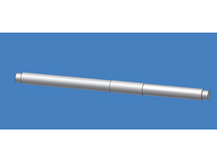 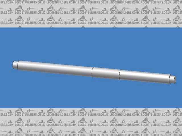
Rescued attachment AxleNSDEV.JPG
The above comments are always meant to be from the above persons perspective.
|
|
|
MikeRJ
|
| posted on 19/12/06 at 08:10 PM |
|
|
I'm sure I have seen split bearings to solve exactly this kind of problem.
A quick google reveals they do exist!
|
|
|
NS Dev
|
| posted on 19/12/06 at 10:20 PM |
|
|
...........pricey though!
Retro RWD is the way forward...........automotive fabrication, car restoration, sheetmetal work, engine conversion
retro car restoration and tuning
|
|
|
NS Dev
|
| posted on 19/12/06 at 10:22 PM |
|
|
quote:
Originally posted by tks
Thats bullchit..
how much you think is the torque?
how much torque do you think a locking system will withstand?
Don't complicate just BOLT it with bushes
its the cheapest en most easyest method.
Tks
I reckon the impact torque on launch from the startline will be of the order of 1200NM minimum, possibly more.
Retro RWD is the way forward...........automotive fabrication, car restoration, sheetmetal work, engine conversion
retro car restoration and tuning
|
|
|
tks
|
| posted on 20/12/06 at 07:16 AM |
|
|
how did you calc this!
1200NM!!!
whats engine torque?
whats prim ratio
whats gearbox prim ratio..
also remember that when you don´t have resistance you don´t have torque!!
Tks
The above comments are always meant to be from the above persons perspective.
|
|
|
NS Dev
|
| posted on 20/12/06 at 08:12 AM |
|
|
0 - 60mph in approx 4 secs on dirt means pretty good resistance!!
The grip level is of a totally different level to a locost type vehicle with little rear suspension travel.
I have seen grassers shear std sierra lobro driveshafts off like carrots on the startline
In my case, the engine peak torque is approx 103NM, primary ratio is 1.935, 1st gear is 2.5, so that is 498NM at the sprocket, then final drive ratio
is 2.5, giving 1245NM @ shafts.
Generally as a rule of thumb you can double those figures as a shock loading when dropping the clutch at peak engine torque rpm, giving around 1000NM
at the sprocket and 2500NM at the final drive sprocket.
That's how I estimated it.
[Edited on 20/12/06 by NS Dev]
Retro RWD is the way forward...........automotive fabrication, car restoration, sheetmetal work, engine conversion
retro car restoration and tuning
|
|
|
MikeRJ
|
| posted on 20/12/06 at 08:19 AM |
|
|
quote:
Originally posted by tks
1200NM!!!
whats engine torque?
whats prim ratio
whats gearbox prim ratio..
You are forgetting that the peak torque experienced under start line conditions (i.e. very rapid clutch release with high RPM) will be down to the
energy stored in the crank, flywheel and clutch, and can be many times higher than the engines peak torque.
This is why "dropping the clutch" on a car is far more likely to cause drive train damage than simply running the engine at peak torque,
which the transmission should be able to sustain indefinately.
[Edited on 20/12/06 by MikeRJ]
|
|
|
MikeRJ
|
| posted on 20/12/06 at 08:23 AM |
|
|
Nat, how about making the shaft in two halves, maybe coupled by some kind of cush drive? This would considerably simplify the assembly/disassembly
issues.
|
|
|
tks
|
| posted on 20/12/06 at 10:15 AM |
|
|
your self are saying it...
but that axle isn´t the final drive!!
sow there isn´t that amount of torque on it...
anyway size can always be increased...
for me the problem is solved..
a 40mm bar with 1 10mm drill wont do nothing with suchs forces...
driveshaft are tube right?
Tks
The above comments are always meant to be from the above persons perspective.
|
|
|
NS Dev
|
| posted on 20/12/06 at 10:18 AM |
|
|
Interesting thought..............
maybe not a cush drive but two 6 bolt flanges, with the final drive "driver" sprocket sandwiched in between, could quite nicely allow me
to shim them together or apart though the bearings to align the sprockets at each end while keeping the centre one(s) aligned as
well...............
nice idea!
Retro RWD is the way forward...........automotive fabrication, car restoration, sheetmetal work, engine conversion
retro car restoration and tuning
|
|
|
tks
|
| posted on 20/12/06 at 11:26 AM |
|
|
mhhh
problem will be then the bolt allocation on 2 flanges
you then cant have a chit between them!
(else you have a woble in the axle)
sow deff CNC job.
Tks
The above comments are always meant to be from the above persons perspective.
|
|
|
NS Dev
|
| posted on 20/12/06 at 12:38 PM |
|
|
quote:
Originally posted by tks
problem will be then the bolt allocation on 2 flanges
you then cant have a chit between them!
(else you have a woble in the axle)
sow deff CNC job.
Tks
eh?
I'm confused!
I make sure the flanges are perpendicular to the shaft (machine flat after welding on) then as long as the sandwich shims are equal thickness all over
there's no problem
Retro RWD is the way forward...........automotive fabrication, car restoration, sheetmetal work, engine conversion
retro car restoration and tuning
|
|
|
tks
|
| posted on 20/12/06 at 01:21 PM |
|
|
False :(
The axles will need to be inline to..
also your sprocket will be centered on the bolts (read as holes) wich you drill in those flanges...
sow in my opinion more problems...
what is the reason for turning in the lathe a long axle??
the size you talk about should stil be build the same way not?? (with the extra thing on the opposide of the knife)
Tks
The above comments are always meant to be from the above persons perspective.
|
|
|
MikeRJ
|
| posted on 20/12/06 at 07:51 PM |
|
|
quote:
Originally posted by tks
The axles will need to be inline to..
If the flanges are square and the ends of the shafts have some kind of centering spigot machined into then then surely you'd just need to bolt
up the flanges, then tighten the bearings down and the shafts should be accurately aligned.
I admit the reason I mentioned a cush drive was to accomodate any small misalignments, but would not be needed with accurate machining.
|
|
|
soggy 3
|
| posted on 21/12/06 at 12:43 AM |
|
|
You seem to be involved in the grasser scene why dont you ask around the guys who have done this before , geoff berisford and z cars spring to mind
they both are usualy at the autosport show in jan.

|
|
|