flak monkey
|
| posted on 22/2/06 at 09:25 PM |

|
|
Pedal Design - Opinions?
Just had a go at designing a set of pedals for my car. Designs are based on the GTS geometry, but not copied.
They are all aluminium (2018 grade), which is where the fun came in:
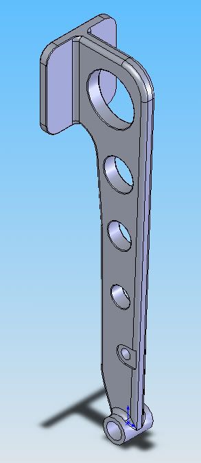
Brake is 10mm thick, and weighs 297g. Thickness reduced at clevis point to 8mm, which leaves that point the weakest. Designed to yeild with an 80kg
person (i.e me) standing on it at 2G deceleration. Is that enough?
Brake pedal pic:
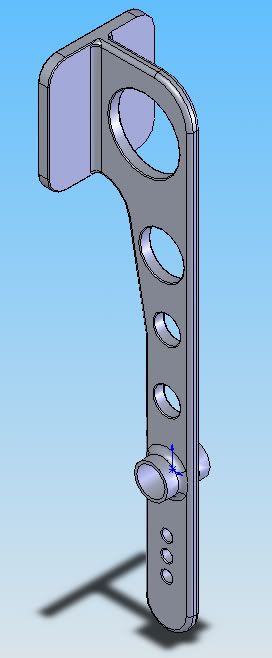
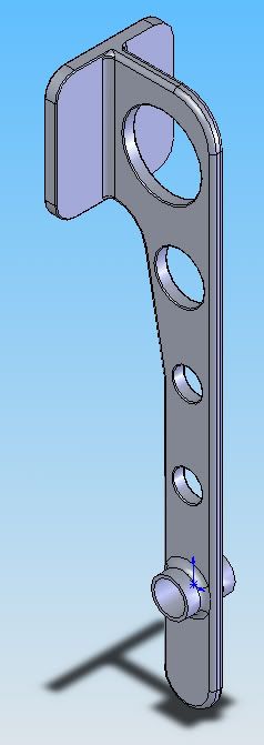
Accelerator and clutch are very similar, both 6mm plate and weigh 180g each. Both will yeild at a load of 1.5G with an 80kg person. Excessive probably
for that application.
Accelerator:
Clutch:
Any opinions or comments appreciated.
Cheers,
David
PS: Anyone know where I can get some 2018 or equivalent plate from? Obviously I dont want much!
Sera
http://www.motosera.com
|
|
|
|
|
JoelP
|
| posted on 22/2/06 at 09:30 PM |

|
|
me personally, id design a little more strength into the brake - 2g isnt that much really, even though your full weight doesnt really hang on it, but
failure would be bad news.
ps, is it a hydralic clutch?
|
|
|
flak monkey
|
| posted on 22/2/06 at 09:40 PM |

|
|
Cable clutch. There are just no holes in the bottom of the clutch pedal as I dont know where to put them at the moment.
Problem is I cant design any more stength into the brake as I am limited by the material The weakest point is where the clevis pin goes through the
pedal. The bit that sits inside the saddle is actually the weakest part. Short of going up to a long clevis (which is huge) I dont think I can do much
about it....unless anyone has any bright ideas!
David
Sera
http://www.motosera.com
|
|
|
ed_crouch
|
| posted on 22/2/06 at 09:57 PM |

|
|
Would that be a UniGraphics model??
Presumably your strength figures are based on an ANSYS buckling analysis...
The design might change a little if you were to use 2 master cylinders in parallel with a balance bar in the middle??
When I was at Uni we tended to design aeroplane parts in 6061 and 7075 tempered to T4 or T6. I never actually machined any though: its probably a
right bugger to work!
Looks good, though. FEA and CAD are really coming within the grasp of the amateur car builder, and it'll result in more professional looking
kitcar builds.
Ed.
I-iii-iii-iii-ts ME!
Hurrah.
www.wings-and-wheels.net
|
|
|
JonBowden
|
| posted on 22/2/06 at 10:01 PM |

|
|
Can't see any point in trying to make that pedal light as failure would be quite bad
Jon
|
|
|
JonBowden
|
| posted on 22/2/06 at 10:03 PM |

|
|
quote:
FEA and CAD are really coming within the grasp of the amateur car builder
Are any free / cheap FEA packages good enough and understandable with a bit of effort
(sorry, don't mean to steal the thread)
Jon
|
|
|
eddymcclements
|
| posted on 22/2/06 at 10:08 PM |

|
|
The brakepedal might resist the 2G forces the first time you stand on it hard...and the second and third. What about the 237th time? The 946th? In my
opinion the lack of resistance to fatigue of aluminium and its alloys rules it out as a suitable material unless it's a pretty hefty forging or
casting. Save weight somewhere else.
Just my tuppence worth,
Eddy
|
|
|
flak monkey
|
| posted on 22/2/06 at 10:08 PM |

|
|
Its a solidworks model actually. FEA with Cosmos. Not a bad package, simple to use. Got it through Uni 
As for making it light, the drilled holes make no difference to where the pedal fails. All bending stresses are carried by the outer edges of
beams.
David
Sera
http://www.motosera.com
|
|
|
ed_crouch
|
| posted on 22/2/06 at 10:09 PM |

|
|
Do a google search on free FEA
or get a "student license". Im *sure* David knows what I mean there...
Ahem.
Ed.
P.S. they are almost all limited in some way though... ANSYS multiphysics is still the big boy, and costs the earth.
As far a CAd goes, SolidWorks is probably the best cheap one. UG, ProE, CATIA (YUK!!!) are all biiiiig money, still.
I-iii-iii-iii-ts ME!
Hurrah.
www.wings-and-wheels.net
|
|
|
ed_crouch
|
| posted on 22/2/06 at 10:11 PM |

|
|
As a small point, David, the area where you have got the pedal thinned down to fit the clevis doesnt appear to allow any pivoting of the clevis
relative to the pedal. Expanding the thinned area to fix this may affect its buckling load.
Ed.
I-iii-iii-iii-ts ME!
Hurrah.
www.wings-and-wheels.net
|
|
|
flak monkey
|
| posted on 22/2/06 at 10:21 PM |

|
|
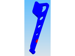
Heres the FEA showing those areas with a safety factor of less than 1.5 with that 2G design load. As you can see its all in that area within the
clevis. I could go up to a 10mm clevis and make a pushrod on the lathe at home to suit. That a reasonable solution?
You are right Ed, theres not quite enough room for the clevis to pivot. There is enough in there to allow a couple of degrees, but it does need
expanding.
David
Rescued attachment failure point.jpg
Sera
http://www.motosera.com
|
|
|
Bob C
|
| posted on 22/2/06 at 10:38 PM |

|
|
I did a similar thing with the brake: apparently the ford spec is 1500newtons on the pedal & even using 8mm steel it was tough to get a safety
factor.
On your design the overstressed bit is where from the look of it the material is in compression due to the leverage exerted by the pedal -
shouldn't the design taper down towards the pedal ? (you effectively have a beam balanced on the clevis). You could make the ally a couple of
inches by 8mm up at the pivot/clevis end???
Bob
|
|
|
greglogan
|
| posted on 22/2/06 at 10:39 PM |

|
|
Saw a brake pedal failing in Corolla rally car in Ireland some time back. It wasn't pretty. Don't know much about thew engineering side of
it but surely a bit more wouldn't hurt?
Women are meant to be loved, not understood.
|
|
|
flak monkey
|
| posted on 22/2/06 at 10:46 PM |

|
|
OK that makes me happier because thats designed for 1600N force on the pedal.
Yes the failure is on the compression side of the pedal. And it was modelled with a beam restrained at the pivot and with a force 5x that at the pad
at the clevis (pedal ratio is 5:1) as that was the simplest way of modelling it I could see.
If I use a 10mm clevis then the overstressed part isnt a problem any more. It just means I will have to make up a custom pushrod at home. Not a major
issue.
[Edited on 22/2/06 by flak monkey]
Sera
http://www.motosera.com
|
|
|
Bob C
|
| posted on 22/2/06 at 10:48 PM |

|
|
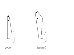
here's a dodgy picture of what I was trying to say above.....
See what COSMOS thinks of it . . . . .
cheers
Bob
Rescued attachment pedals.GIF
|
|
|
flak monkey
|
| posted on 22/2/06 at 10:52 PM |

|
|
Yep, that gives a safety factor of 1.6 for the design as opposed to only 1.05 that i had originally. Much better. Just needs a bit of tweaking i
think.
These are floor mounted pedals by the way...but the pivots are offset from eachother like the GTS pedals.
Sera
http://www.motosera.com
|
|
|
Liam
|
| posted on 22/2/06 at 11:15 PM |

|
|
With all due respect it's still a scary design if you ask me! 6mm ally plate just aint up to the job imo. In engineering, for a critical
component (this is certainly critical) you work to a safety factor of at least 4 and commonly 10. If you factor in the fatigue you get with ally you
might even work to a safety factor of 40. A strong guy panic braking with all his leg strength, with his back restrained by the seat could probably
yield your pedal in a single operation!
Furthermore your design isn't stiff in torsion which will further stress it if the pedal is pressed nearer to it's edge.
Check out designs of tilton or AP racing pedal boxes for example. Or lotus elise pedals. They all will have a way higher safety factor than 1.6!
Please dont use this design in a car, even in steel!
Elise Pedals
CAD view of thinner throttle pedal
Elise brake pedal extrusion is about 20mm thick.
Liam
|
|
|
flak monkey
|
| posted on 22/2/06 at 11:23 PM |

|
|
OK, point taken (brakes 10mm). Just figured that the material i specced on isnt suitable either. So bugger it.
*Note to anyone else thinking about this - Ali pedals arent a good idea.*
Will make them in stainless steel instead, or maybe i will just buy a set!
David
Sera
http://www.motosera.com
|
|
|
ed_crouch
|
| posted on 22/2/06 at 11:27 PM |

|
|
When us aero types are desgning a bit of aeroplane, we go with a factor of safety of 1.5 for yield stress, and 2 for UTS.
But, we also eliminate single point failures, so there is always a "backup", or alternative route.
A brake pedal structural failure is a single point of failure of the braking system(catastrophic failure too), unless you consider the handbrake an
alternative!!!!!! I woudn't!!!
Ed.
P.S. I think that a brake pedal might be better made out of steel (EN1A is nice and easy), and run a higher FoS. But, this is still a good exercise,
and can safely be used for the clutch and gas pedal.
I-iii-iii-iii-ts ME!
Hurrah.
www.wings-and-wheels.net
|
|
|
ed_crouch
|
| posted on 22/2/06 at 11:31 PM |

|
|
Also remember that sometimes steels (7800kg/m^3 and UTS of about 300MPa) CAN give lighter solutions that Aluminium (about 2700kg/m^3, 60MPa?????
IIRC!).
Certainly where fatigue cycling is an issue the S/N curve (load stress Vs no. of cycles until failure) for steel is much better.
Hence why the ally locost chassis is a "unique" idea. No bugger'll trust one.
I thoroughly agree with using CAD to optimise designs though.
Ed.
I-iii-iii-iii-ts ME!
Hurrah.
www.wings-and-wheels.net
|
|
|
C10CoryM
|
| posted on 22/2/06 at 11:43 PM |

|
|
Do your calculations take into account that pretty much anyone can squat twice their body weight?  In the driving position you are nearly in a
seated leg press excersize. You can leg press MUCH more than you can squat. Not to mention that you may be stomping the pedal, not smoothly applying
weight. Also you will not be applying perfectly straight force into the pedal. There will be twisting forces as well. I have seen production car
pedals (rougly 1"X 0.25" carbon steel) get bent/twisted in panic braking. Even saw a guy with a VW take part of his dash apart and blow
up his M/C from stomping the brakes In the driving position you are nearly in a
seated leg press excersize. You can leg press MUCH more than you can squat. Not to mention that you may be stomping the pedal, not smoothly applying
weight. Also you will not be applying perfectly straight force into the pedal. There will be twisting forces as well. I have seen production car
pedals (rougly 1"X 0.25" carbon steel) get bent/twisted in panic braking. Even saw a guy with a VW take part of his dash apart and blow
up his M/C from stomping the brakes  . I had to replace a bunch of parts to get him going again. He was maybe 65kg. I am the same weight as you
and I don't think 6mm of aluminum stands a chance . I had to replace a bunch of parts to get him going again. He was maybe 65kg. I am the same weight as you
and I don't think 6mm of aluminum stands a chance  . .
Cheers.
"Our watchword evermore shall be: The Maple Leaf Forever!"
|
|
|
Liam
|
| posted on 22/2/06 at 11:46 PM |

|
|
Yeah the aerospace industry is unique in that sense. But with tracable materials, strict lifing of components and double and tripple redundancy, you
can get away with lower safety factors (in order to make the things light enough to get in the air).
Just another point, flak - to get a more accurate picture of the stress throughout the whole pedal, I'd have though you'd want to restrain
both the pivot and part of the pedal surface, then load the clevis. This will get the pedal bending as it would in reality.
Liam
|
|
|
Liam
|
| posted on 22/2/06 at 11:55 PM |

|
|
P.S. Ed - f.y.i my ally flywheel is 7075-T6. My mate who machined it from my solidworks model reported it was very nice to work with! Excellent
properties too. He has also made some 6061 parts for my mate's mountain bike, which went well too.
Liam
|
|
|
C10CoryM
|
| posted on 23/2/06 at 02:35 AM |

|
|
Ok, Ive been home all day with a cold so Im bored. With a scale between me and a wall in a seated position I can easily push approx 280lbs (127KG)
with my right leg before my wall made a CRACK noise and I stopped  . I know I have pressed much harder than that while driving. I am not that
strong but I do mountain bike so I probably come up about average for a 180lb guy (82kg) . I know I have pressed much harder than that while driving. I am not that
strong but I do mountain bike so I probably come up about average for a 180lb guy (82kg)
Hope this helps.
"Our watchword evermore shall be: The Maple Leaf Forever!"
|
|
|
flak monkey
|
| posted on 23/2/06 at 08:19 AM |

|
|
quote:
Originally posted by Liam
Just another point, flak - to get a more accurate picture of the stress throughout the whole pedal, I'd have though you'd want to restrain
both the pivot and part of the pedal surface, then load the clevis. This will get the pedal bending as it would in reality.
OK tried that, and yes you get different results. The the pedal fails at the weld between the pivot tube and the pedal arm.
I was modelling the pedal with a force on the pad equal to the force being applied by your foot, then restraining the pivot as it cannot move in the
car, and applying a force of 5x the pad pressure to the pivot (since the pedal ratio is 5:1). Whats wrong with this?
Sera
http://www.motosera.com
|
|
|


