derf
|
| posted on 24/10/05 at 01:27 PM |

|
|
new home built A arms
The jig was good enough that the lower arm can be fliped over and fit in either way. The 2 uppers are exactly alike. I fishmouthed all the tubes with
my handy dandy trusty angle grinder, lots of fitting and a little bit of trial and error. I did screw up my first try at a lower arm (not
pictured).
When I get a chance I will post up the dimensions fo the jig. These are built around using s10 steering knuckles, and this design is adjustable for
camber, and caster. Toe will be adjustable with the steering rack.
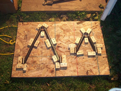 
before welding in the jig
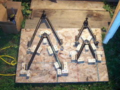 
before and after in jig
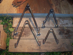 
with and without hardware
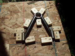 
a closer view of the upper arm jig
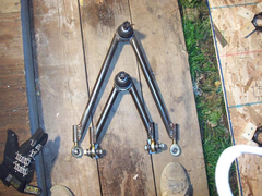 
size difference between upper and lower
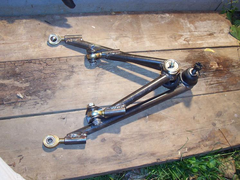 
upper and lower together
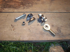 
The brackets clamp around the heim joint
Yes, I am trying to use a hi-tech looking front suspension, still undecided as to if it should be a pull rod (like steve grabber) or a pushrod. I am
actually leaning very heavily toward the pull rod type.
This will save on space, be adjustable, and just look bad ass (plus it works too)


The ball joints are again from the dirt track guys, but the label marked them as pinto (us version) ball joint.
They are similar to press in units, but they screw in. The collars on my A arms are threaded too and the ball joint just screws in. I need to cut my
old suspension tabs off before I can mount these, then I am going to work on mounting the shocks (which I still havn't done).
Someone I work with (who is a homebuilt nay-sayer) explained to me how the way the heims are that I can also correct any inconsistency in the chassis.
My chassis is off center by less than 1/16", but he says that it will be a real big deal.I don't think that 1/16" matters.
And a pic of what the old suspension looked like:
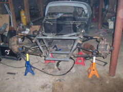 
front suspension complete
|
|
|
|
|
JoelP
|
| posted on 24/10/05 at 07:40 PM |

|
|
looks very nice, overall a neat solution. I would be a little concerned over the fact that both lower legs weld onto the circle that houses the ball
joint, but i suppose that the ball joint will strengthen this somewhat. Personally, i would weld in a small fillet to help this area resist braking
forces 
|
|
|
derf
|
| posted on 24/10/05 at 08:09 PM |

|
|
Yes I agree, that topic has been covered here.
After some input from a few local "experts" I am going to box in an inch back from the circle, and also using a U shaped 1" tube
weld a support brace a bit further back.
|
|
|
Peteff
|
| posted on 24/10/05 at 08:10 PM |

|
|
It would look stronger with a gusset in there like the bottom mount on a standard setup. I don't think the 1/16th is going to make any
difference to your car derf, I had a Mini with one wheel 3/4" further back than the other and it drove fine for everyday use.
yours, Pete
I went into the RSPCA office the other day. It was so small you could hardly swing a cat in there.
|
|
|


