hellbent345
|
| posted on 10/4/09 at 04:05 PM |

|
|
Any stiffness experts?
 
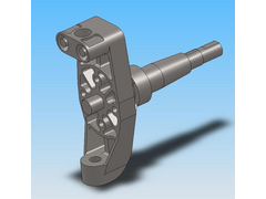
MACHINED UPRIGHT 2
 
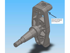
MACHINED UPRIGHT 1
Designing this upright for my college project, doing some FEA on it ive hit a brick wall to improve it really, does anyone know of anything i could
change on it to improve its strength? This is strength from a force on the bearing surfaces of the spindle in an upwards direction.
Thanks al
|
|
|
|
|
Howlor
|
| posted on 10/4/09 at 04:35 PM |

|
|
Fillet where your arrow is pointing, don't like the sharp stress raiser in this area.
Steve
|
|
|
hellbent345
|
| posted on 10/4/09 at 05:01 PM |

|
|
I cant  , thats where they join together, they are 2 parts but for analysis i have to join them as one, same story with the base of the spindle, the
spindle is the highest problem area, but i cant put a radius down where it really needs to be as the spindle itself needs to be bolted in. , thats where they join together, they are 2 parts but for analysis i have to join them as one, same story with the base of the spindle, the
spindle is the highest problem area, but i cant put a radius down where it really needs to be as the spindle itself needs to be bolted in.
|
|
|
britishtrident
|
| posted on 10/4/09 at 06:00 PM |

|
|
Based on the above i don't think your model is valid. You need to look at your assumptions and BC's
Taking axle stub as an example the usual way to attach a axle stub is to use a single large nut on the revese side -- pretension of the nut of
course introduces a compress pre-load in the boss into which it fits.
Likewise the bolt on boss for the top ball joint will introduce compressive pre-loads.
[I] “ What use our work, Bennet, if we cannot care for those we love? .”
― From BBC TV/Amazon's Ripper Street.
[/I]
|
|
|
wozsher
|
| posted on 10/4/09 at 06:53 PM |

|
|
Are they machined or cast ?
|
NOTE:This user is registered as a LocostBuilders trader and may offer commercial services to other users
|
NS Dev
|
| posted on 10/4/09 at 07:01 PM |

|
|
Well......
At a glance it looks pretty well thought out to me, both from a strictly mathematical point of view and a "reality" point of view
regarding manufacture and serviceability/adjustability.
If our student at work came up with things like that I would have nobody to take the p155 out of!
There is always a way to improve something, but, assuming its cast, I would go as-is!
Retro RWD is the way forward...........automotive fabrication, car restoration, sheetmetal work, engine conversion
retro car restoration and tuning
|
|
|
NS Dev
|
| posted on 10/4/09 at 07:03 PM |

|
|
PS take it the steering arms locate onto the 4 holes on a PCD round the inside of the stub?
Retro RWD is the way forward...........automotive fabrication, car restoration, sheetmetal work, engine conversion
retro car restoration and tuning
|
|
|
rachaeljf
|
| posted on 10/4/09 at 08:21 PM |

|
|
In my humble opinion, your structure looks a bit overelaborate. If your primary loading is vertical loads on the spindle, you should try and maximise
the second moment of area (I) of the upright to resist bending in the relevant axis. By inspection your upright has its weaker "I" axis
resisting the primary loading, so it's inefficient.
The large voids formed above and below the stub are trapezoidal in shape. This means that braking/acceleration forces are resisted by bending of the
three individual webs in their weaker axes. The stiffness/strength of the upright under braking forces would be greatly improved by adding webs across
the diagonals of the voids to triangulate them.
Personally I would use rectangular hollow sections with crush tubes welded in. A hollow structure maximises stiffness and strength for a given weight
of material. On your model, try adding say, 2 mm thick "cover plates" over the front and back of your upright so it's all enclosed.
You will find a massive increase in the upright's strength and stiffness.
Cheers R
|
|
|
hellbent345
|
| posted on 10/4/09 at 09:49 PM |

|
|
Thanks for all replies, could you clarify the bad points rachel, i dont know what you are refering to with the I axis? Also i have the facilities to
machine from solid billet but not the expertise to weld a fabricated upright together accurately and with sufficient strength so cant do that
unfortunatley  And the bolt on top ball joint adjuster is very important to me to still include at this stage, so id need to have a design that
still has this included. And the bolt on top ball joint adjuster is very important to me to still include at this stage, so id need to have a design that
still has this included.
I understand and take your point about 2nd moment of area, and that hollow sections are best, but bit difficult for me to machine those, the only way
i could do that would be to weld, and im a cack welder lol
Thanks Ns dev, and yes the steering arm will be on there, along with the caliper mounts, allowing it to be reversed for front rear steer.
It will be machined for now from billet alloy steel (EN24), unless anyone thinks it looks strong enough to be done in ally  The large wall section
in the middle is 6mm wide for a sense of scale - its also roughly the same max dims as a cortina upright. The large wall section
in the middle is 6mm wide for a sense of scale - its also roughly the same max dims as a cortina upright.
Finally, british trident, what would preloading do to the strength of the upright, detract from it or add to it? the software im using doesnt support
adding preload of bolts etc i dont think, just wondering how much difference it will make? I need to have the analysis for my project really, so if im
coming out with useless information i need to know how to shift the results and why, to explain in my report?
Thanks again everyone
Alan
|
|
|
Badger_McLetcher
|
| posted on 10/4/09 at 09:56 PM |

|
|
It looks perty 
I can't really see any way of strengthening that design without making it heavier. You may gain some small amounts by thickening the webs. Also
as rachaeljf turning the lightening holes into triangular shapes. Could you extend the webs on the rear out further maybe?
BTW if this message seems a little garbled it may be because my brain is currently happilly pickling in cider 
If disfunction is a function, then I must be some kind of genius.
|
|
|
rachaeljf
|
| posted on 11/4/09 at 05:40 PM |

|
|
I see you have left a central web in around the spindle area, this would entail milling from both sides. It would be better use of material to move
this web to the inside face. Leave some web material covering the rest of the inside face of the upright. This will improve bending stiffness. Also
triangulate the trapezoidal voids as I said before. Apart from that, I think you have done as well as you can for a billet part.
Your top ball joint arrangement is fine, but don't bother with the rebating around the ball joint spindle; you are removing material in the
wrong place there.
Sorry if I confused the issue with the "I" axis. If you sliced horizontally through your upright you would see more or less a rectangular
cross section. A rectangle has a larger "I" value about its short axis than about its long axis. You can say a rectangle has
"strong" and "weak" I axes. Your primary loading bends the upright about the rectangle's long (weak) axis. This means
you have not made optimum use of the material. However, there are other constraints on your choice of section because you have to accommodate the
spindle and steering arm bolts. Overall, your upright is doing a good job.
Hope that made some sense! (Edited for bad grammar)
[Edited on 12/4/09 by rachaeljf]
|
|
|
britishtrident
|
| posted on 12/4/09 at 07:59 AM |

|
|
The way to build a valid model is you have to understand the engineering of the component before building the model. Modern integrated 3d cadcam
systems now make it much too easy to automesh anything without considering the implications on the validity of the model.
Modelling of any bolted joint is complex, modelling a bolted joint as one piece may often be perfectly valid if the area you want results from is
distant enough the you can apply Saint Vennant's Principle. In terms of mechanical engineering FEM Saint Vennant's Principle can be
summed up as local features have local effects .
But you cannot under any circumstances model a bolted joint as a one piece solid then expect local results from it.
The bolted joint is probably too complex for you too model.
In a bolted joint the bolts are always under tension and the bolted faces of the material are under pre-compression. These pre exising forces are
super imposed on the loads case BUT it gets more complex the faces that are bolted together cannot transfer tensile forces -- tensile forces
can only be transfered by the bolts, and the bolts don't transfer compressive forces.
[I] “ What use our work, Bennet, if we cannot care for those we love? .”
― From BBC TV/Amazon's Ripper Street.
[/I]
|
|
|
rachaeljf
|
| posted on 12/4/09 at 05:38 PM |

|
|
Following on from britishtrident's post:
If you want to get good marks for your report, you need to explain where your model deviates from actuality, what you have done to make your model
closer to reality and what you may have approximated, showing why it won't significantly affect your results. I realise that may be a big ask,
but an appreciation of the limitations of FEA software - the biggest one being "garbage in = garbage out"! - will set you above the
average student. Knowing what to expect to see in your model's behaviour under loading is a big part of this.
As long as your FEA software doesn't get upset, you can model through-bolting by adding some bosses to your bolt/nut bearing faces to represent
washers. Then apply equal and opposite forces, representing the tension in your chosen size bolts, spread over the bearing faces of the
"washers."
You can do similar but more complicated tricks to represent the forces generated in your balljoints' tapered pin connections.
BTW, it's "Saint-Venant" if you wish to look him up (no offence meant btrident!).
Cheers R
|
|
|


