paulf
|
| posted on 3/6/11 at 12:21 PM |

|
|
quote:
Originally posted by Doctor Derek Doctors
In my conclusion mounting inside will give roughly a 5:10 installation ratio, mounting outside will give a 6:10 installation ratio thus outside would
be stiffer with the same springs.
Hope that helps.
Are you sure that you got this the correct way around? surely the nearer vertical the damper is then the stiffer the effective spring rate.
Paul
|
|
|
|
|
mrwibble
|
| posted on 3/6/11 at 12:29 PM |
|
|
i'm confused, as a leyman, DDD's proposal and numbers seem very convincing... but then i can't claim to understand what the numbers
mean...
what was your job title again DDD?
|
|
|
Doctor Derek Doctors
|
| posted on 3/6/11 at 12:31 PM |
|
|
quote:
Originally posted by paulf
quote:
Originally posted by Doctor Derek Doctors
In my conclusion mounting inside will give roughly a 5:10 installation ratio, mounting outside will give a 6:10 installation ratio thus outside would
be stiffer with the same springs.
Hope that helps.
Are you sure that you got this the correct way around? surely the nearer vertical the damper is then the stiffer the effective spring rate.
Paul
Yes thats what it says. 6:10 (outside) is stiffer than 5:10 (inside).
Not the clearest sentence I have ever written I know.
Designer and Supplier of the T89 Designs - Single Seater Locost. Build you own Single Seater Racecar for ~£5k.
Plans and Drawings available, U2U or e-mail for details.
Available Now: The Sports Racer Add-On pack, Build a full bodied Sports Racer for Trackdays, Sprints and Racing.
www.t89.co.uk
www.racecarwings.co.uk
callan@t89.co.uk
|
NOTE:This user is registered as a LocostBuilders trader and may offer commercial services to other users
|
Doctor Derek Doctors
|
| posted on 3/6/11 at 12:39 PM |
|
|
quote:
Originally posted by Neville Jones
quote:
Originally posted by Bare
Simply Try to mount the shocker unit as vertically as absolutely possible. ..
Save yourself a maths exercise to tell you exactly that .
Wouldn't overly worry about structural 'niceities' as even the suspension pickup points on these Locost chassis are just daft/poor
. The mount ears have been documented to fatigue off due to their poor placement and inadequate support.
Shock mount 'strength' is the least of your worries.
[Edited on 1/6/11 by Bare]
That statement above is about right on every count. What oriface DDD pulls his info from I don't know,( Wikipedia?or the same place as the
ship's engineers?)
The numbers are pulled from TrolleyJacks stated suspension layout, put into a sketch of his supsension and the the wheel moved 10mm at a time in CATIA
V5, no opinion, no expectation, just numbers from an unbiased CAD box.
The numbers are clearly listed for all to see, yes mounting on the outside gives a higher installation ratio but mounting on the inside gives a more
constant rising rate and rate of rising rate. As clearly stated
I don't know what your problem is, you have provided no figures, no facts, just the same old BS heresay, you have added nothing positive and
made no effort to even read the numbers. I on the other hand tried out the two options that TrolleyJack had open and simply provided a list of numbers
back and said what I would do if it were my car. What TrolleyJack reads into those numbers and does is upto him/her (It's a neutral name)
Once again you just bring pointless negativity and zero help.
[Edited on 3/6/11 by Doctor Derek Doctors]
Designer and Supplier of the T89 Designs - Single Seater Locost. Build you own Single Seater Racecar for ~£5k.
Plans and Drawings available, U2U or e-mail for details.
Available Now: The Sports Racer Add-On pack, Build a full bodied Sports Racer for Trackdays, Sprints and Racing.
www.t89.co.uk
www.racecarwings.co.uk
callan@t89.co.uk
|
NOTE:This user is registered as a LocostBuilders trader and may offer commercial services to other users
|
Doctor Derek Doctors
|
| posted on 3/6/11 at 12:45 PM |
|
|
quote:
Originally posted by mrwibble
i'm confused, as a leyman, DDD's proposal and numbers seem very convincing... but then i can't claim to understand what the numbers
mean...
what was your job title again DDD?
They aren't my numbers really, I just put Trolleyjacks suspension into a standard 2D layout of front suspension and then moved the wheel by 10mm
at a time and wrote down the numbers that came out. they would have been the same had anyone done them
Job title? Well technically I'm listed as Mechanical Engineer / CATIA V5 Designer but at the moment there is stuff from Fluid and Thermo
dynamics, Man' Eng and Material involved as I'm working on a major project for a future Formula 1 car.
Designer and Supplier of the T89 Designs - Single Seater Locost. Build you own Single Seater Racecar for ~£5k.
Plans and Drawings available, U2U or e-mail for details.
Available Now: The Sports Racer Add-On pack, Build a full bodied Sports Racer for Trackdays, Sprints and Racing.
www.t89.co.uk
www.racecarwings.co.uk
callan@t89.co.uk
|
NOTE:This user is registered as a LocostBuilders trader and may offer commercial services to other users
|
mrwibble
|
| posted on 3/6/11 at 02:00 PM |
|
|
quote:
Originally posted by Doctor Derek Doctors
quote:
Originally posted by mrwibble
i'm confused, as a leyman, DDD's proposal and numbers seem very convincing... but then i can't claim to understand what the numbers
mean...
what was your job title again DDD?
They aren't my numbers really, I just put Trolleyjacks suspension into a standard 2D layout of front suspension and then moved the wheel by 10mm
at a time and wrote down the numbers that came out. they would have been the same had anyone done them
Job title? Well technically I'm listed as Mechanical Engineer / CATIA V5 Designer but at the moment there is stuff from Fluid and Thermo
dynamics, Man' Eng and Material involved as I'm working on a major project for a future Formula 1 car.
well i'm sure your a very clever man. i don't understand why someone has been so rude to you for trying to help someone with their
build...
|
|
|
britishtrident
|
| posted on 3/6/11 at 04:13 PM |
|
|
quote:
Originally posted by mrwibble
quote:
Originally posted by Doctor Derek Doctors
quote:
Originally posted by mrwibble
i'm confused, as a leyman, DDD's proposal and numbers seem very convincing... but then i can't claim to understand what the numbers
mean...
what was your job title again DDD?
They aren't my numbers really, I just put Trolleyjacks suspension into a standard 2D layout of front suspension and then moved the wheel by 10mm
at a time and wrote down the numbers that came out. they would have been the same had anyone done them
Job title? Well technically I'm listed as Mechanical Engineer / CATIA V5 Designer but at the moment there is stuff from Fluid and Thermo
dynamics, Man' Eng and Material involved as I'm working on a major project for a future Formula 1 car.
well i'm sure your a very clever man. i don't understand why someone has been so rude to you for trying to help someone with their
build...
+1
[I] What use our work, Bennet, if we cannot care for those we love? .
― From BBC TV/Amazon's Ripper Street.
[/I]
|
|
|
Doctor Derek Doctors
|
| posted on 3/6/11 at 04:57 PM |
|
|
quote:
Originally posted by britishtrident
quote:
Originally posted by mrwibble
quote:
Originally posted by Doctor Derek Doctors
quote:
Originally posted by mrwibble
i'm confused, as a leyman, DDD's proposal and numbers seem very convincing... but then i can't claim to understand what the numbers
mean...
what was your job title again DDD?
They aren't my numbers really, I just put Trolleyjacks suspension into a standard 2D layout of front suspension and then moved the wheel by 10mm
at a time and wrote down the numbers that came out. they would have been the same had anyone done them
Job title? Well technically I'm listed as Mechanical Engineer / CATIA V5 Designer but at the moment there is stuff from Fluid and Thermo
dynamics, Man' Eng and Material involved as I'm working on a major project for a future Formula 1 car.
well i'm sure your a very clever man. i don't understand why someone has been so rude to you for trying to help someone with their
build...
+1
Cheers guys
Clever man? I wish! Just lucky when it comes to getting jobs I think (sshhhhhhhhh..... don't tell anyone I work with)
Designer and Supplier of the T89 Designs - Single Seater Locost. Build you own Single Seater Racecar for ~£5k.
Plans and Drawings available, U2U or e-mail for details.
Available Now: The Sports Racer Add-On pack, Build a full bodied Sports Racer for Trackdays, Sprints and Racing.
www.t89.co.uk
www.racecarwings.co.uk
callan@t89.co.uk
|
NOTE:This user is registered as a LocostBuilders trader and may offer commercial services to other users
|
Neville Jones
|
| posted on 3/6/11 at 05:46 PM |
|
|
DDD,
Considering that my work has involved motorsport design, and I have many years of experience, and my statements have been corroborated by at least two
other bona fide engineers, then I have every right to question the extremely poor solution you have put forward to the gent asking the question.
To lay the coilover at the angle you suggest, will impart high loads into the top mount and wishbone, and also give undesireable behaviour to the
system.
My explanation was quite simple, and states what is considered to be the accepted normal practice when designing a suspension system of this type. As
I have done far too many times past.
Working in F1 doesn't make anyone a genius or expert, sometimes quite the opposite, and maybe more than a little lucky, as you pointed out.
And as I've stated many times, there is far too much wrong information on this forum, and the internet in general, and if I can stop just one
person from coming to grief because of these misleading statements, then I can say I've done good.
Cheers,
Nev.
[Edited on 3/6/11 by Neville Jones]
|
|
|
procomp
|
| posted on 3/6/11 at 05:50 PM |
|
|
Hi
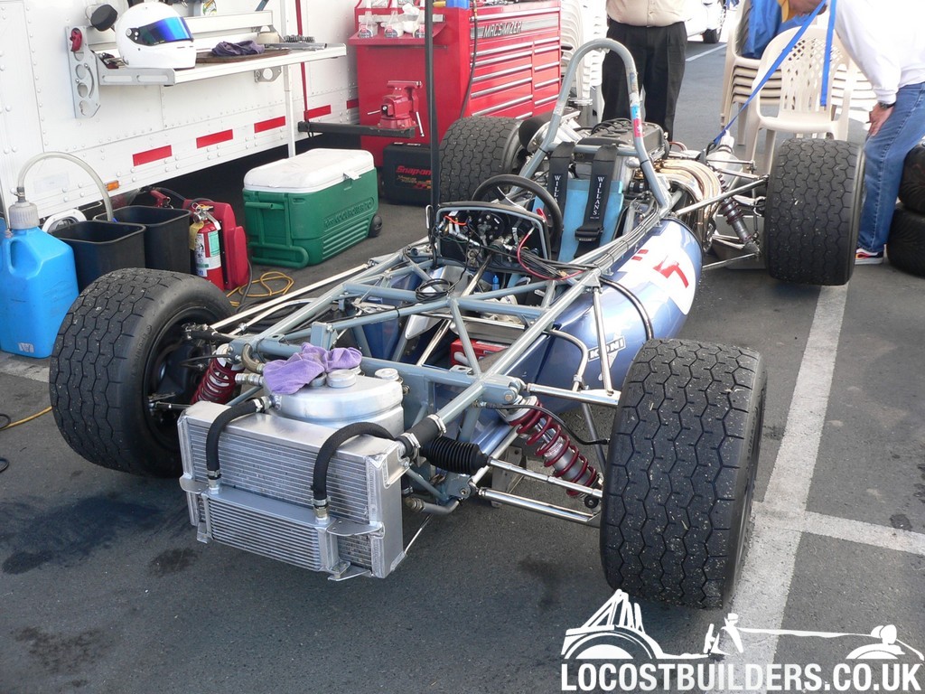
One quick glance at that lot on the pics shows that worrying about a few mm of travel on the damper is the last of your worries. Id be way way more
concerned about the camber gain problems your going to have with that layout on the pickup points of the arms. But as it stands simply move the base
damper mount out as close to the bottom ball joint as is practical and mount the top mount out on the side of the chassis to gain as much damper
travel per wheel travel as possible. You can use a basic ruler for that.
But then again assuming this is just a ROAD use car leave as is and stop worrying. It is still far better than whats available from some of the kit
manufacturers with the top bracket in either position.
Cheers Matt
|
|
|
Trollyjack
|
| posted on 3/6/11 at 06:11 PM |
|
|
Just read all the comments above and my head is now spinning
What to Do now ??????
TrollyJack
|
|
|
Doctor Derek Doctors
|
| posted on 3/6/11 at 09:17 PM |
|
|
quote:
Originally posted by Neville Jones
DDD,
Considering that my work has involved motorsport design, and I have many years of experience, and my statements have been corroborated by at least two
other bona fide engineers, then I have every right to question the extremely poor solution you have put forward to the gent asking the question.
To lay the coilover at the angle you suggest, will impart high loads into the top mount and wishbone, and also give undesireable behaviour to the
system.
My explanation was quite simple, and states what is considered to be the accepted normal practice when designing a suspension system of this type. As
I have done far too many times past.
Working in F1 doesn't make anyone a genius or expert, sometimes quite the opposite, and maybe more than a little lucky, as you pointed out.
And as I've stated many times, there is far too much wrong information on this forum, and the internet in general, and if I can stop just one
person from coming to grief because of these misleading statements, then I can say I've done good.
Cheers,
Nev.
[Edited on 3/6/11 by Neville Jones]
We're all waiting with bated breath for you to come out with anything other than petty negativity, rambling arguments and personal insults....
but then again that seems to be all you can come out with.
Seriously, get a life.
Designer and Supplier of the T89 Designs - Single Seater Locost. Build you own Single Seater Racecar for ~£5k.
Plans and Drawings available, U2U or e-mail for details.
Available Now: The Sports Racer Add-On pack, Build a full bodied Sports Racer for Trackdays, Sprints and Racing.
www.t89.co.uk
www.racecarwings.co.uk
callan@t89.co.uk
|
NOTE:This user is registered as a LocostBuilders trader and may offer commercial services to other users
|
flak monkey
|
| posted on 3/6/11 at 09:34 PM |
|
|
While Nev is not particularly tactful in his reply, his information is as well founded as it comes I am afraid. Coupled with Matts comment above.
With outboard shocks on a seven type car its nearly impossible to get the ideal set up as they sit at such a shallow angle. If you are that determined
to get it as good as you can then start looking at inboard shocks and at better suspension geometry overall.
Sera
http://www.motosera.com
|
|
|
mark chandler
|
| posted on 3/6/11 at 10:16 PM |
|
|
Shock on outside point, get the bone mount as far out as possible as recommended by Matt, personally I do not like forcing the wishbone to act as a
lever, you just load up both ends anyway.
You do need to try and get more travel on that shock, its nearly closed in droop, this achieves this.
My qualifications are none BTW 
This is the front of a winning Brabham for reference, okay its 30 years old so a load of old tat!
nb/ do not agree with all the nasty comments, pointless and rude on both sides.......
[Edited on 3/6/11 by mark chandler]
|
|
|
Neville Jones
|
| posted on 4/6/11 at 09:56 AM |
|
|
quote:
Originally posted by Doctor Derek Doctors
Seriously, get a life.
 I've got a sense of humour instead. You might get the same. I've got a sense of humour instead. You might get the same.
If yourself, and one or two other wannabe's who want to be engineers, stopped posting wildly incorrect and misleading, and sometimes downright
dangerous information, then I wouldn't be wanting to correct same.
There's nothing wrong with being a cad jockey, or a ships engineer, be happy in that, and stop trying to be something you're not.
Research your subjects properly, and post from a base of knowledge and experience.
Cheers,
Nev.
|
|
|
JF
|
| posted on 4/6/11 at 11:08 AM |
|
|
Nev, with all respect to all your wisdom and experience. Can you back your story up with numbers and proven examples? Like you say yourself... there
is a lot of false information out there. Why should anyone assume your information is indeed right.
What went wrong with DDD's calculations? Instead of burning him to the ground, maybe you could give him some pointers where to look out for or
some secret parameter we meager mortal humans don't know about.
And yeah maybe DDD doesn't present himself in the smartest way possible, and yeah he might often give wrong advice. But instead of just burning
him to the ground, maybe you could help him a little so he might get it right next time. And help many people to the right information.
Because not only are you burning DDD down to the ground. Trolleyjack still doesn't know how he should do it.
Oh please allmighty Neville Jones, please share some of your infite wisdom with us lower humans.
PS: I for one would be interested to learn a bit more about this subject as I'm trying to work out a chassis design. Wich might get built
someday, but till I get the chance to do so I enjoy doing some design work.
PSS: Yes you should read this post with your sense of humor turned on.....
|
|
|
britishtrident
|
| posted on 4/6/11 at 11:44 AM |
|
|
When somebody shouts about how bright they are and denigrates others we know exactly what they are.
About 20 years back I used to share a lunch table with a guy who was later nominated for a Nobel prize he was very quiet and unassuming but he was
the real deal.
[I] What use our work, Bennet, if we cannot care for those we love? .
― From BBC TV/Amazon's Ripper Street.
[/I]
|
|
|
Neville Jones
|
| posted on 4/6/11 at 04:25 PM |
|
|
OK, sense of humour turned up and sarcasm alarm turned down..... And aware that a couple of wannabe's are gunning for me... ( If they had
any sort of engineering education, then they would not be saying what they are, and would understand what I've said. Flakmonkey IS an engineer,
thus his comments.)
Short of taking a lot of time to do a bundle of sketches, I'll try and explain in words. (A picture is worth a thousand words, I know, but
anyway....)
Draw a bottom wishbone, inner pivots and coilover mount at the outer end.
Now draw a coilover at the outer pivot, at 90degrees to the wishbone.
Any load put upwards into the coilover, from the wishbone, at this point will be directly along the axis of the coilover, so the full rate of the
spring can react to it.
Now draw the coilover at an inclination inwards towards the chassis, with the bottom pivot still in the same place on the wishbone.
A vertical load at the coilover pivot is reacted only by the vertical component of the coilover. As it is inclined, the coilover will be pushing
outwards on the wishbone as well. This should be fairly easy to see. As the top of the coilover is now inclined even more, the outward push increases
in relation to the sine of the inclination angle, and the vertical decreases with the cosine. Thus, a heavier spring is needed to give the same
vertical force at the pivot, as would be required if the coilover was vertical or close to it.
At 10 degrees inclination, the cosine is 0.9848, the sine is 0.1736. So, if the spring in the coilover is pushing along its axis with 100 lb force,
then 17.36 lb force wqould be acting outwards, and 98.48 lb force would be acting vertically at the wishbone pivot. At 15 degrees, these figures go to
96.59, and 25,88. 20 degrees then gives 93.96 and 34.2. If you graphed these, you would find that they would follow a sinusoidal graph. Up to about
20 degrees, things are fairly linear, but most would prefer to keep the angles as low as possible. Once you get past 20 degrees, the vertical
component decreases at an increasing rate, and the horizontal increases.
That about sums it up.
So, if you put the coilover at 90 degrees to the wishbone when at the max travel up of the wishbone, the force seen by the wishbone will be increasing
as the cosine decreases. Rising rate. Quite simple.
With a Locost book situation, it is difficult to achieve what I've just outlined. However, the top of the coilover should be as near to vertical
as is possible geometrically. This will probably put the top mount some distance from the chassis, and needs to be dealt with by adding an extra tube
laterally, attached to the chassis and picking up the top coilover mounts. This would do the same job as what is commonly known as a 'strut
brace' on tin tops.
Clear as mud!
Cheers,
Nev.
[Edited on 4/6/11 by Neville Jones]
|
|
|
JF
|
| posted on 4/6/11 at 09:26 PM |
|
|
Thank you for this constructive post Nev. I'd offer you a drink if we were in a bar. But sadly I don't feel like swimming across the pont
tonight 
It's hard to find good sollid information on the net. And well I'm no engineer, nor do I have any experience designing cars or even parts
for cars. Although I'm working on both. I'm a mechanic who works a lot with metal, hydraulics and electronics but not an expert on any
field. And won't claim that I am either.
But I believe in doing things right, certainly when it comes to suspension etc. And therefor it's always nice to obtain some knowledge from
someone who has been there and actually knows a thing or 2 about it.
So might I ask you, and others offcourse, to atleast supply the TS with the info he needs. Preferably with some sort of fundation, as there is way to
much bogus info out there. If besides that you feel the need to burn anyone who gives a wrong answer... well have fun...
|
|
|
mrwibble
|
| posted on 6/6/11 at 06:41 AM |
|
|
out of interest, for a coil over mounted inboard with rocker arms, what would be the optimum, 45 degrees?
[Edited on 6/6/11 by mrwibble]
|
|
|


.jpg)


