i don't understand balance bars
blakep82 - 15/12/08 at 11:54 PM
i have to admit, i really don't understand balance bars,
i don't know how well i'll be able to explain this, or understand the answer  but here goes...
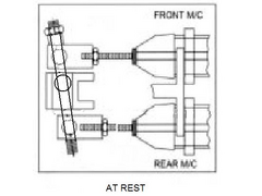
going by this

the balance is adjusted by how far the clevises are screwed onto the push rods? is that correct?
why do the nuts on the threaded bar need to be locked? surely all that does is screw through the clevises? and link them together through the pedal?
woudn't screwing the bar in and out just move the bar?
i don't get it 
MikeR - 16/12/08 at 12:27 AM
The bit in the middle (spherical bearing) that the pedal touches that in turn moves the bias bar isn't the full size of the pedal. therefore when
you twist the bias bar, the bit that the pedal touches actually moves closer / further from one or the other master cylinder.
Therefore when you press the pedal more pressure if placed on either hte left or right master cylinder.
Let me put it another way, in the middle of your diagram, the middle picture. The line that is pointing towards the middle section. Imagine only that
little bit was connected to the pedal. If you moved that line further down hte page and then pressed against it - which master cylinder would get more
pressure?
blakep82 - 16/12/08 at 12:42 AM
ah i get it now, i didn't realise the bearing in the pedal moved side to side when you turn the bar.
so when setting up, is screwing the clevises on the push rods like a coarse adjustment, and the balance bar fine adjustment?
Dusty - 16/12/08 at 01:34 AM
Nope. Screwing the individual piston rod into the clevis does not alter the balance. It changes where the balance bar sits at rest and thus alters the
potential stroke for that piston. As a common setup is discs (plus large pistons) at the front and drums (small pistons) at the rear you will usually
find the front piston needs a longer stroke than the rear. Thus you set the front m/c rod long and the rear m/c rod short so the balance bar sits at
an angle at rest. As you press the pedal both pistons move forward but the rear m/c piston brings the shoes into solid contact with the drums early in
the stroke and the rod on the rear m/c pretty much stops moving. The front m/c rod needs to move further to bring the front shoes into firm contact
with the discs. Thus the pedal keeps going forward and the angle of the balance bar changes to allow this. The bar is usually setup as shown in your
diagrams. M/c bore size is chosen to minimize this effect. However increasing bore size of M/c increases fluid moved per unit of stroke but reduces
effective effort transferred to the brake piston and alters the balance so you move the balance bar to compensate and then the pedal has increased
leverage on the bigger piston but a reduced range of movement and you're back to square one. I'll stop now, my brain hurts.
[Edited on 16/12/08 by Dusty]
Dusty - 16/12/08 at 02:13 AM
Done a quick mod to your pic to show position of the balance bar fulcrum bearing in the pedal, with the balance adjusted to max power to the front.
This also shows one of the problems in that the balance bar is a thick rod and will potentially contact the pedal bearing tube surface at both ends of
it's stroke effectively becoming solid so you may not get the range of skewing movement you might hope for. Greatest range of skew is with the
balance bar fulcrum in the centre position. Thus most end up with the smaller piston serving the front brakes despite their needing most fluid volume
to operate but that way they get the greater pedal effort transferred where it's needed by the smaller piston and rely on the maximal skew
movement with the balance fulcrum fairly central to allow enough piston movement. Must be easier with discs all round.
Well that's as I understand it.
[Edited on 16/12/08 by Dusty]


Rescued attachment bias.JPG
 but here goes...

