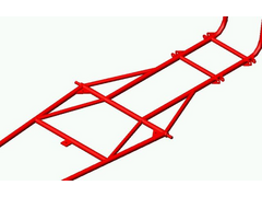


The pic shows what I had just today morning.....
Rescued attachment 041125-1.JPG

A mistake on my computer took away my CAD data, I just have to start it again...


The pic shows what I had just today morning.....
Rescued attachment 041125-1.JPG
And the pedal box, also gone away to a beter world..
What a CB I am......
Rescued attachment Pédalier.JPG
That totally BLOWS! 
What happened? You looked in your recycle bin? There may be other ways of recovering data because even when it is deleted, it's only the pointer
to the data that is deleted. the actual data stays on the drive until it is overwritten by new data... Maybe try posting a plea for help in the
Computer Problems section?
Steve
quote:
Originally posted by sgraber
What happened?
Great to be able to model your plans like this. Looks really good. My suggestion would be to try to place your suspension pick-up points on chassis
node points, and to triangluate all the rectangles that you can. Also, try to make the 4 main longitudinal members members continuous without any
dog-leg. If you can do this, then there is a chance you don't have to use any steel sections greater than 20mm square with wall thickness of
1.5mm, and you can get a complete chassis for under 70kg including roll-over protection. Cheers, Brian
[Edited on 29/11/04 by Ratman]
Thanks for coments..
I plan to place the suspension anchors on legs made with stronger tube (50x30x2,7) to allow changing of positions during the tuning and setup phase.
And also triangulation of each square with round tube of lower diameter.
Like this (picture) it weights 56 kg, it's in 30x30x1,6.
Of course this weight doesn't comprise the weld, the missing braces and some paneling. The 70 kg target seems possible.
Maybe it will be possible to grab some honneycomb in the factory's trash and make a full sandwich paneling of the cockpit area.
I think the kink in the side members is good for stiffness because it makes possible a smooth load path between front box and central area.
To be confirmed by a stiffness analysis I will try to do the folowing days..
[Edited on 1/12/04 by Aloupol]
Rescued attachment Chassis041130.JPG
Better make the engine section connect to the nodes of the passenger section. (in other words; the engine bay will get wider in the front. Try not to
end tubes in the middle of other tubes, try to let them go to the nodes.
I'm sure you'll find that rebuilding your model, after a loss of all data, will go soooooo much faster than the first one. All the thinking
has been done......
Good luck!
If you can't achieve straight runs or node-to-node members, then bracing them like in the single-seater base below will spread the loads more
evenly. That way you can keep the wall thickness down to the minimum too.


Rescued attachment chassis01.jpg
Bracing to the nodes is essential for a stiff chassis. Tubes are great in tension/compression but not bending so you always need to get to a corner
and also triangulate where possible.
One thing you should consider is building balsa models of some of your designs. You will really get a good feel for how stiff the final chassis will
be by twisting the model. Alan Stanisforth recommends this in his book "High Speed Low Cost". I built at least 4 different models while
designing my chassis and each version was stiffer and stiffer. It works a treat!
Graber
Yes, the balsa model seems a good way. I saw it in "Chassis engineering" from Herb Adams.
I've got a soft for tubular structures computing but it's easier to feel things with something in the hands than with too much numbers in
the head....
Taught about it and you're right, the weak point in my design is the kink in the upper side beam which allows it to bend under axial load. In the
lower member it's not an issue due to the cross members.
Gonna sort this tonight.