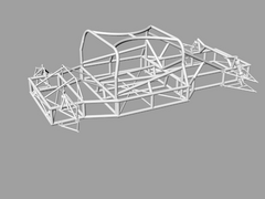

Rescued attachment chassis1.jpg

Hi all, just found this web site to day while try to do so research while I was meant to be working, I am mad about all things cars like most of you
seem to be here so I guess I am in the right place, I am in the process off finishing a vtec powered mini and have caught the car building bug big
time and want to take a leap in to the deep end and build my own design of car from scratch, I am a computer engineer by trade but cars are my first
love, I download rhino’s 3d/cam demo and off ive gone, I am just looking for constructive criticism to what you think of my first attempt at
designing my first very own chassis its a mid mount layout design drawn to 1/10 scale to house a Chevy small block mated to a porche g50 box, please
feel free to comment.


Rescued attachment chassis1.jpg
Don't you hate it when you have a great reply written and then it crashes on you.....
Anyway, the gist of it was....
Hi and welcome...
I may have misunderstood you, sorry if I have, but you should never draw or model in anything other than 1:1 scale.....view or print however you need
but always model 1:1
Your choice of powerplant would suggest you are an Ultima fan?
Looks good, and robust! I'd suggest some foward down-tubes to connect the main roll cage to the front suspension/shock area. As it is, it looks
like it has low torsional rigidity.
Also try to have triangles everywhere. Said another way, try to have at least three tubes form a junction, not two, which allows bending. Yet
another way to look at it, you want every tube junction to not move in any direction, right?. That means you want it static in three degrees of
freedom. That calls for three tubes!
[Edited on 23/2/04 by kb58]
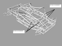
New support bars am i along the right lines here.

Rescued attachment new1render.jpg
Good! Geez this thing should be as strong as a tank. As an example of what I meant about tube junctions, there are quite a few. The problem is describing in words where they are... It's like I said though, anywhere tubes are welded together, there should be at least three tubes meeting at the node and not less then that. With just a little shifting about of tube ends, you can make it much stiffer and not add any weight. Just examine all the junctions, all must have at least three meeting up!
Thanks for all the help there probably going be 100`s of more questions to answer to come but it looks like im in the right place.
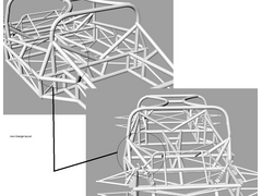
I no im a pain but with a bit on reworking i thinks im going down the right lines now (i think) :-0 triangles

Rescued attachment reartrifount.jpg
Exactly. It's just a matter at looking at all the junctions and asking yourself if, by moving a tube, you can increase the number of tubes
meeting at a junction. The more the better. Obviously some tubes can't move, while others can. It's all a big compromise...
[Edited on 23/2/04 by kb58]
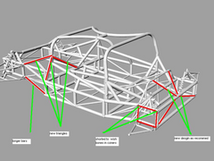
Welcome aboard. I've marked up your first chassis with a few comments:


Description
1) Firstly, I've added a slightly different bracing at the front marked in green. This would result in more tubes meeting at the same point (as
indicated by KB)
2) If at all possible try not to feed loads into the middle of tubes. For example the pickup points for the front wishbones (marked in red)
3) Same point as above for the rollhoop diagonals (marked in purple)
4) The central section marked in yellow will probably add little to rigidity. If you want them to divide the cabin, I would use smaller diameter
tubes.
5) If you carried the tubes at the rear (marked in brown) further back that would help stabilize the rear a little better. As it is now you will get
some bending introducted in to the main rails under some situations.
6) Again there is a problem feeding loads into the middle of a tube as highlighted in blue. Sometimes you just can't avoid this (in which case
make sure the tube is of sufficient diameter and wall thickness). However, try as hard as you can to avoid this situation.
7) A general comment I will make is that the rear looks pretty flimsy. This is a problem with a lot of mid engined cars. If possible try and
triangulate this area, even if it means the tubes have to be detachable to get the engine in/out.
I would highly recommend either doing some FEA or building a balsa model and just trying out different configurations (this is what I did). Its very
hard to predict by eye how stiff a chassis is. I've done a lot of experimentation and can tell you that one or two missing tubes can make a
massive difference.
Below is a picture of my chassis that may give you a few ideas. There are a few tubes missing marked in red.
Description
There are a bunch more photos on my website: www.projectlmp.com
Hope this helps.
Here are some more modifcation do to my chassis as recomened. thanks agian for all the help.

Rescued attachment chassis24th.jpg
Your chassis reminds me of the Maserati 'Birdcage' racer.
They used to say that if you let a canary loose inside the chassis and it got out there was a tube missing!
I want to put over 450 bhp though it so its going to have to be a busy chassis
The tubes that sits sort of diagonally across the door way, the one with the "center post," both ends need to move to the junction points of other tubes.
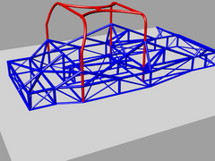
Hi all thanks for all the comments ive reworked the whole chassis with a use-able bulkhead and alot more trianglated sections any more constructive
criticism would be a help

Rescued attachment 26threworked1.jpg
There you go, I see lots of good tube junctions! Good work! BTW, the grey color seemed to worked better as far as being able to see all the
tubes.
[Edited on 26/2/04 by kb58]
Just had a look at this thread, the chassis is very very similar to the various designs by Lee Noble, most notably the Ultima chassis, which incidentally also uses a chevy V8 and Porsche G50 'box!!