mark chandler
|
| posted on 14/1/07 at 06:08 PM |

|
|
Fireblade clocks, struggling to get anywhere
Hi all,
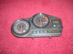
I have a set of blade clocks, these came without a loom so I have pieced out all the wires from the multiplug and started to wire up.
All easy things are now done, lights indicators et al, but I cannot get anything out of the rev counter or speedo (digital trip shows mileage covered
and temp gauge works okay).
I,m trying to run these from a 893 blade engine, this seems to have a slightly later ignition module as it includes TPS wiring, anway the yellow green
tacho lead is live so it should be okay.
On the blade the odometer sensor has three wires, where do these go and any ideas on which pins the tacho goes on ?
Cheers Mark
 
Rescued attachment PC140041.jpeg
|
|
|
|
|
esn163
|
| posted on 14/1/07 at 06:19 PM |

|
|
Hi
Speed sensor wires are:
pink/green - speed pulse to clocks
green/black - sensor (-) on clocks and also T to earth
black - sensor live from fuse box
tacho is the yellow/green from ECU should go straight to clocks
HTH
Ed
[Edited on 14/1/07 by esn163]
Indy Build Photos
** Build pages **
Photo Bucket Pics
|
|
|
the_fbi
|
| posted on 14/1/07 at 07:02 PM |

|
|
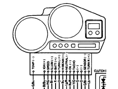
Not sure if you have this.
Looking at the back of my clocks (same as yours) the connector is actually 2 rows, so not sure how it matches up with the pic.
 
Rescued attachment dashplug.jpg
|
|
|
mark chandler
|
| posted on 14/1/07 at 08:03 PM |

|
|
Hi,
The problem I have is no loom so I cannot identify the correct pins by wire colour....
From the rear I have 2 x set of 6 pins top row and 2 x set of 4 pins bottom row.
The bottom row controls mostly lights, lhs is batt powered ie indicator and head light, rhs looks for an earth to trigger so neutral and oil.
I there any chance you could provide me with correct pins by colour ? However you count I can work out by what I now know.
Cheers Mark
|
|
|
the_fbi
|
| posted on 14/1/07 at 08:32 PM |

|
|
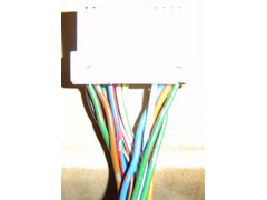
Didn't even know I had the bike loom hanging around.
Sorry for the massive glare.
2nd pic, the green with black trace is on one of the short rows on its own.
 
Blade Dash Wiring 1
[img]/upload/dashcon2s.jpg[/img]
[Edited on 14/1/07 by the_fbi]
|
|
|
mark chandler
|
| posted on 14/1/07 at 11:02 PM |

|
|
Great, thanks very much for this, hopefully I can progress, either that or bin it and go Acewell.
Cheers Mark
|
|
|
mark chandler
|
| posted on 14/1/07 at 11:42 PM |

|
|
Trying to wprk my way through this is as far as I get, please can you confirm
|
|
|
the_fbi
|
| posted on 15/1/07 at 08:02 PM |

|
|
I think your 2 rows of pins got crossed at some point.
This is looking at the wire entry to the back of the loom connector. So should match up with looking at the rear of your clocks.
|
|
|
mark chandler
|
| posted on 15/1/07 at 09:00 PM |

|
|
Cheers,
I think mine clock is slightly different as I have added a couple more earths on the LHS top and Yippee I now have a tacho and dragging the speedo
wire across the frame I get up to 70mph.
I have tried using an ABS sensor to trigger the speedo with zero success so must now work out what I need, I suspect a coil and magnets will get that
up and running.
Many thanks Mark  
|
|
|


