carnut
|
 posted on 3/2/05 at 10:52 PM posted on 3/2/05 at 10:52 PM |

|
|
Cush in drivetrain
Does anyone have a cush in there drivetrain?
I'd like to take a bit of shock loading away from my gearbox as ive already broken it once.
Do people just fit a rubber coupler like the sierra one in the shaft or do they use one instead of a UJ?
thanks
Carnut
Oh, forgot to mention about the massive clonking as I change gear as low rpm/load. It also makes a huge clonk a I engage 1st from neutral.
|
|
|
|
|
mangogrooveworkshop
|
| posted on 3/2/05 at 11:24 PM |
|
|
And where do we come by these mr snoopy?
|
|
|
carnut
|
| posted on 3/2/05 at 11:37 PM |
|
|
Thanks Snoopy, Ill see if I can get hold of one.
|
|
|
Rorty
|
| posted on 4/2/05 at 06:47 AM |
|
|
Some commercial flexible couplings use a PU star in them and are finely balanced for high RPM. They are designed to protect gearboxes and would lend
themselves to your situation, though you may need to do some machining/drilling to make one fit..
Cheers, Rorty.
"Faster than a speeding Pullet".
PLEASE DON'T U2U ME IF YOU WANT A QUICK RESPONSE. TRY EMAILING ME INSTEAD!
|
|
|
carnut
|
| posted on 4/2/05 at 11:09 AM |
|
|
PU star?
|
|
|
Rorty
|
| posted on 4/2/05 at 12:05 PM |
|
|
PU =polyurethane.
Star = a star shape.
The male side of the flexible coupler interlocks with the PU star and the female does as well, but neither the male nor female halves actually touch
each other.
The pic below shows the general set-up, but there are dozens of styles and fitments.
 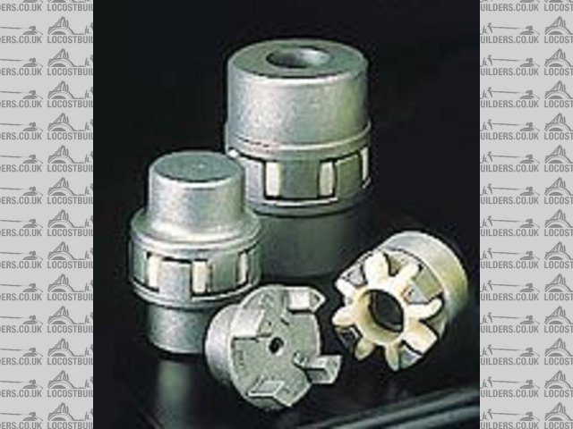
Rescued attachment coupler2.jpg
Cheers, Rorty.
"Faster than a speeding Pullet".
PLEASE DON'T U2U ME IF YOU WANT A QUICK RESPONSE. TRY EMAILING ME INSTEAD!
|
|
|
Hellfire
|
| posted on 4/2/05 at 12:21 PM |
|
|
I think Bailey Morris do a TRT (Torque Resilient Tube) propshaft. I assume it will be similar to the Cossie shaft but could be wrong.
Bailey Morris
Give em a call, get a price and then let us all know how much
|
|
|
ko_racer
|
| posted on 4/2/05 at 01:27 PM |
|
|
I've just got my propshaft from bailey morris. It came out at £290 all in, which is pretty expensive. I went for the TRT with centre bearing
and sliding joint. The overall prop working length was about 145cm
I think the TRT added around £60 to the price and an extra half inch to the diameter of the section with the TRT (so took it to around 2.5"
diameter)
|
|
|
locoboy
|
| posted on 4/2/05 at 01:55 PM |
|
|
Yeah thats about right Ko, Ox paid about that for his bailey morris one too.
It doesnt clang as much as his old one on the R1 motor did - in fact it doesnt clang at all iirc.
ATB
Locoboy
|
|
|
Kissy
|
| posted on 28/2/05 at 01:29 PM |
|
|
I've just called Bailey Morris and they have agreed to take my existing 2-piece propshaft and modify it with a torque transfer tube. They have
quoted £110 (+ VAT I assume). Reckon on a couple of days turnround. Includes balancing the whole shaft again. Not too bad I thought. They were a
bit wary of taking another shaft, but were OK when I said it was new.
|
|
|
tks
|
| posted on 28/2/05 at 08:58 PM |
|
|
well
talking about drive trains...
i was wondering
how everybody did this part of the job.
in my case i have used all the sierra bits
(both) including the flexible mount in the middle.
i have bolted the rubber end (normally to the gear box) to the differential and the knee part to my bike engine.
the reason for doing soow is that my bike engine is a V4 and the output shaft isn't in the middle (VFR 800)
soow i needed more lengt the better(less angle)
my question is how did everybody align his / her engine????
are their vibrationsss..???
who would like to make/has pics of his her construction??
TKS
 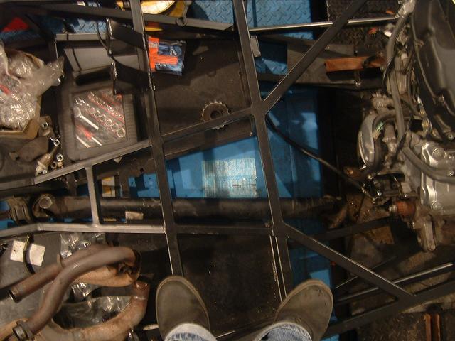
Rescued attachment 24122004 013 small.JPG
|
|
|
Kissy
|
| posted on 1/3/05 at 08:24 AM |
|
|
I aligned the engine (CBR1000F) by hooking up the axle, propshaft and engine in the chassis, I then juggled the engine to offer the nearest to
straight run into the propshaft. I did this by having the chassis blocked at intended running height and used blocks of wood and my mate to steady
the engine, I then fabricated the stays as required. By engine is rigid mounted (semi-stressed) in the chassis. Took about one day from start to
finish. If I was doing it again I'd mount on expanding rubber bushes. That said the vibration is not at all bad.
Anybody know if, instead of going the Bailey-Morris route, I can modify my propshaft to have a sierra rubber donut by the diff to act as a cush drive,
I cannot see any reason why not?
|
|
|
tks
|
| posted on 1/3/05 at 09:55 AM |
|
|
well
well i have mounted 2 rubbers in the drive chain that permit the axle to shake free...
the one with the 3 holes (6 holes instead) is called here a "flector" that one i hooked up to the differential soow there i permit a couple
of degrees of movement//continous...
then in the middle as you see the pic i mount the bearing etc// mount for the other axle..
i hate vibrations..and their are a strange enemey..
weight is one of the key factors talking about vibrations.. but offcourse good alignment is key factor.
The bike engine has the plus plus that all the parts are weight carefully and balanced carefully soow in fact it runs a lot better than a car 4
cilinder etc..offcourse the low torque is also a advantage...
i mounted my engine also in one hole day.... i had 3 rulez to look at:
- ground clearance
- headclearance for body work (bonnet)
- and i wanted it the most the the right in the chasis (less angle with prop).
then i took a meter and measured the distance between a paralell chasis tube and the clutch flange. For knowing if i mounted it in line.
(i was asuming that flange was 90degrees with the rest of the engine....)
i also bolted it on as a semi stressed member. and cant wait to try it because i have a bit of fear with vibrations..etc..
another rule i have heard of talking about knee pieces is that you always need to have the same angle at both sides of the prop.
see pic..
is this true???
TKS
 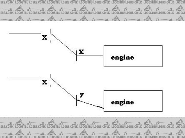
Rescued attachment enginemount.JPG
|
|
|


