Spyderman
|
| posted on 26/9/05 at 01:15 PM |

|
|
Avoneer, why do you want a longer lever for the gearbox?
Any change in lever throw can be done by using different lengths on an "L" shape lever as in your 1st picture.
All you need to do is work out how far you want the paddle shifter to move. Then find out how far the gear selector arm moves.
If the pushrod from your paddle-shift is moving 5mm and you need the selector to move 25mm, all you need is a 5:1 ratio on "L" lever. So
an "L" lever with pivot to short end of 15mm and pivot to long end of 75mm would give travel required.
The "L" lever could very easily be made from 3mm steel.
Hope I haven't misunderstood your question!
Terry
 
Spyderman
|
|
|
|
|
andrew.carwithen
|
| posted on 26/9/05 at 03:43 PM |

|
|
Pat,
I've measured the length of the alloy gear lever you won on ebay and it is 115mm (4 1/2" between centre of splined hole and centre of
toe-peg. between centre of splined hole and centre of
toe-peg.
(I've also got the later rear-set type linkage if you want me to measure the 'L' shaped lever of that?)
Andy.
|
|
|
Avoneer
|
| posted on 26/9/05 at 03:49 PM |

|
|
Hi Spidy, no, you haven't misunderstood the question.
I fogot to say that the because the original one is too short, the rod from the gear selector on the engine would have to be at about a 60 degree
angle to clear the prop, so a longer arm would let this push rod sit vertically which would make everything else easier so it wouldn't have to
all be on an angle like Ox's first top pivot.
I can then use the "L" to adjust as necessary with a much better angle for both rods.
Hope that makes more sense now,
Pat...
No trees were killed in the sending of this message.
However a large number of electrons were terribly inconvenienced.
|
|
|
Avoneer
|
| posted on 26/9/05 at 03:51 PM |

|
|
Cheers Andy.
That brings the first (lower) joint to just where I want it.
Just the top one to finalise now.
Pat...
No trees were killed in the sending of this message.
However a large number of electrons were terribly inconvenienced.
|
|
|
billy
|
| posted on 26/9/05 at 05:08 PM |

|
|
That lever comes from a yamaha rd 350lc im sure of it, ive owend lots of those bikes
luego-lo-cost finished,vauxhall 16v 2.0,twin 45s de-dion rear set up
|
|
|
ChrisGamlin
|
| posted on 26/9/05 at 05:18 PM |

|
|
Pat, if you get really stuck, you could try speaking to Westfield
The lever they sell as part of their gearchange kit is about the size you need because it too uses a vertical rod so needs the length to clear the
prop. You can see it in the middle of the pic here, they might sell you one on its own maybe?

|
|
|
Avoneer
|
| posted on 27/9/05 at 06:34 PM |

|
|
Cheers Chris, but the one that arrived today is perfect.
This is what arrived:
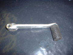 
Rescued attachment 1.JPG
No trees were killed in the sending of this message.
However a large number of electrons were terribly inconvenienced.
|
|
|
Avoneer
|
| posted on 27/9/05 at 06:35 PM |

|
|
So I cut of the flange holding the rubber on and removed the rubber.
Then tapped the bar:
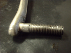 
Rescued attachment 2.JPG
No trees were killed in the sending of this message.
However a large number of electrons were terribly inconvenienced.
|
|
|
Avoneer
|
| posted on 27/9/05 at 06:38 PM |

|
|
Slid my rose joint on the threaded stub and put a nut on it.
Bottom mount sorted - dead easy and perfect for the job, and if the stub ever snaps/bends, I can just cut it off and drill throught the gear selector
lever and bolt the rose joint on:
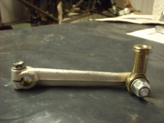 
Rescued attachment 3.JPG
No trees were killed in the sending of this message.
However a large number of electrons were terribly inconvenienced.
|
|
|
Avoneer
|
| posted on 27/9/05 at 06:40 PM |

|
|
Just the top bit to think about again.
Simplist thing I can think of is using 3mm steel plate looking like the following pic. and held in place with two lugs on the chassis and a bolt
through the bottom pivot hole.
Anyone any ideas as to what type of bearing surface I can use on this pivot point?
Pat...
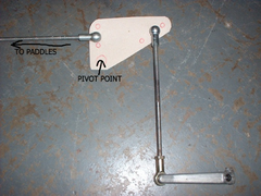 
Rescued attachment 4.jpg
No trees were killed in the sending of this message.
However a large number of electrons were terribly inconvenienced.
|
|
|
Avoneer
|
| posted on 27/9/05 at 06:41 PM |

|
|
Obviously, the lower gear seletor lever will be a right angles pointing into the picture.
Pat...
No trees were killed in the sending of this message.
However a large number of electrons were terribly inconvenienced.
|
|
|
ChrisGamlin
|
| posted on 27/9/05 at 07:00 PM |

|
|
Hi Pat
It looks like you need similar to what Ive got mounted horizontally for my R1 rocker.
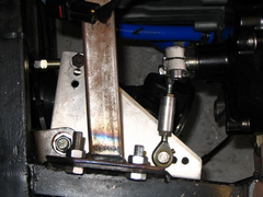 
Gearchange rocker top
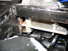 
Gearchange rocker drivers side
As you can see, its made of two bits of ally, a bit of solid bar about 5cm long thats been drilled in the lathe to make the pivot bush, and a
triangular piece of thick plate with a hole drilled in one corner for the bar to pass through, plus obviously small holes for the rod ends to bolt to.
I was intending on eventually making another one with a couple of bearings in it, but this works absolutely fine pivoting on a bit of 10mm steel bar
with some copperslip in there, no slack at all and silky smooth. The only slight issue is that you'll need to get your welder mate to TIG the two
bits together unless you can be fancy and make it a press fit.
|
|
|
Avoneer
|
| posted on 27/9/05 at 07:36 PM |

|
|
Hi Chris.
Yep, that's almost what I'm looking for, although the traingular plate will be vertical above and just in front of the pedal box.
Does it just pivot on the solid bar with a 10mm hole through the centre of it and a piece of threaded rod with a nut top and bottom?
Cheers,
Pat...
No trees were killed in the sending of this message.
However a large number of electrons were terribly inconvenienced.
|
|
|
ChrisGamlin
|
| posted on 27/9/05 at 07:43 PM |

|
|
Yep, the steel pivot bar is tapped top and bottom and tightened up until the steel bracket on the chassis just starts to close up, stopping any
significant vertical float without binding it up.
To do it this way you need to have a long pivot to spread out the load, otherwise it could twist or wear quickly. Because the pivot is about 5-6cm
high, the tolerences dont have to be to the nearest thou' in order to get a nice slack free pivoting action, although you'd want to do it
in a lathe with a decent drill bit obviously.
|
|
|
Avoneer
|
| posted on 27/9/05 at 07:49 PM |

|
|
Cheers Chris.
Will have to ponder on this some more.
I'm liking the idea of a press in bearing of some kind.
May just let it pivot on the shoulder of a 12.9 bolt yet!
Did you sell your seats by the way?
Cheers,
Pat...
No trees were killed in the sending of this message.
However a large number of electrons were terribly inconvenienced.
|
|
|
ChrisGamlin
|
| posted on 27/9/05 at 08:03 PM |

|
|
Yep, sold them to stevebubs.
|
|
|
Avoneer
|
| posted on 27/9/05 at 08:06 PM |

|
|
Oh well, missed a good pair there!
Pivot - how about two rose joints mounted on a plate with 5mm gap between them with the plate between them and a piece of threaded rod through both
centres bolted on each side?
Pat...
No trees were killed in the sending of this message.
However a large number of electrons were terribly inconvenienced.
|
|
|
ChrisGamlin
|
| posted on 27/9/05 at 08:20 PM |

|
|
quote:
Originally posted by Avoneer
Oh well, missed a good pair there!
 
I have visualisation of what youve described but I might be wrong, so fancy drawing a diagram? 
|
|
|
Avoneer
|
| posted on 27/9/05 at 09:20 PM |

|
|
Hope this makes sense:
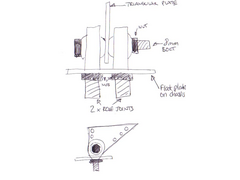 
Rescued attachment 1.jpg
No trees were killed in the sending of this message.
However a large number of electrons were terribly inconvenienced.
|
|
|
ChrisGamlin
|
| posted on 27/9/05 at 09:42 PM |

|
|
Hmm, Im not sure that will work too well to be honest, rod ends wont actually give you a movable bearing surface when mounted like that, the plate
will just rub against them which is not how they are designed to work, and the plate will want to twist on the pivot when you put force through it
because of its lack of thickness not spreading out the twisting forces.
|
|
|
ChrisGamlin
|
| posted on 27/9/05 at 09:49 PM |

|
|
Actually looking at it again if you clamp it all up tight I guess the rod end balls will rotate and give you a decent bearing surface. I still think
the plate will try to twist too much and it will gradually start moving in the way Ive described above, rather than the rod ends giving the rotational
movement.
If you mounted the rod ends further apart and made up a plate with a much thicker pivot length like mine, then that should work OK though, as the
wider surface will spread out the load much more.
[Edited on 27/9/05 by ChrisGamlin]
|
|
|
Avoneer
|
| posted on 27/9/05 at 11:00 PM |

|
|
Aaaaaaa, so that's why ST use two rod ends almost 12" apart!
All makes sense now!
Ok, both rod ends far apart with solid 12mm bar in between them will a 8mm threaded bit on each end that goes through the rod ends.
Triangle plate then welded to middle of the bar.
That should do the job.
Watch this space.
Pat...
No trees were killed in the sending of this message.
However a large number of electrons were terribly inconvenienced.
|
|
|
Avoneer
|
| posted on 29/9/05 at 11:07 AM |

|
|
How about using a wishbone eye and polybushes between two lugs and the arms welded on to the eye?
That would be cheap and simple???
Pat...
No trees were killed in the sending of this message.
However a large number of electrons were terribly inconvenienced.
|
|
|
ChrisGamlin
|
| posted on 29/9/05 at 05:19 PM |

|
|
Poly bushes dont really give you a very friction free movement, OK for suspension but probably a bit sticky and imprecise for the gearchange. It may
also be too flexible side to side still - think of a live axle'd car without a panhard rod to picture what I mean....
What you could do is get a decent bearing to go inside the widhbone eye. I bought two bearings for my steering column that were IIRC about 20mm wide
wth a 1" OD, 5/8" ID. one of those pressed into a 1" ID wishbone type eye pivoting on a 5/8 steel pivot would do the job well, the
bearings were only around £5 each ISTR so it shouldnt cost a lot to do it.
Chris
|
|
|
Winston Todge
|
| posted on 29/9/05 at 08:16 PM |

|
|
This is a very interesting thread as I'm planning on fabbing up a paddle change, obviously minus the CNCed ST paddles as I think they'll
be a little more than I can afford!?
Chris.
|
|
|


