
(credit for R1 engine and figures to dpcars)
[img][/img]

..........of my new project. 
(credit for R1 engine and figures to dpcars)
[img][/img]
not giving much away then!! ]I think theres a lack or ehh engine mounts
[Edited on 17/2/07 by grahamgg]
quote:
Originally posted by chris mason
very minimalist, wouldn't it be a good idea to at least give the 2 poor sods a seat to sit on
Chris
Based on some new anti-grav seats I presume? 


Some wheels might be useful .... or is it a new kind of Skidoo?
He's using the Bose suspension technology and fitting it to the driver/passengers arses...
Anyone modelled some seats in Solidworks?
Thought not, smart arses 
is that an R1 engine,
You can see the air ride suspension better here 
And yes it is an R1 engine. Goto DPcars website it you want a free copy.
[img][/img]
i know i know, it'a s sand buggy from star wars, i always wanted one of those.
Have you sold your old car yet?
Ah a new style of hair dryer looking at the positions of those tubes on the motor. Is the front bit a magazine rack ? 
Its not a new concept,should look like this when its finished


Rescued attachment popular_science_hoverl.jpg
Is it just me or are both of those blokes steering? That would certainly make for some novel handling...
Pete
never mind that, in that seating position they will be crippled in a few miles

quote:
Originally posted by diyer
Have you sold your old car yet?
might have a problem there with sharp edges at the front when it comes to sva. oh and where are the indicators.

very good. better than I could do at the moment.
indicators? you can use your arms !
hmm, nice,
here is mine... I made the mistake of not measuring properly how much space I need..... so the front needs to be made longer and rear shorter... when
I get some time to finish my build table I will make some real measurements and a rough lifesize outline of the chasis...
I also made some simulations of the front suspension geometry...so I need to fit those pickup points into my model..
sidepods look dangerous, but add massive torsionall stffness..
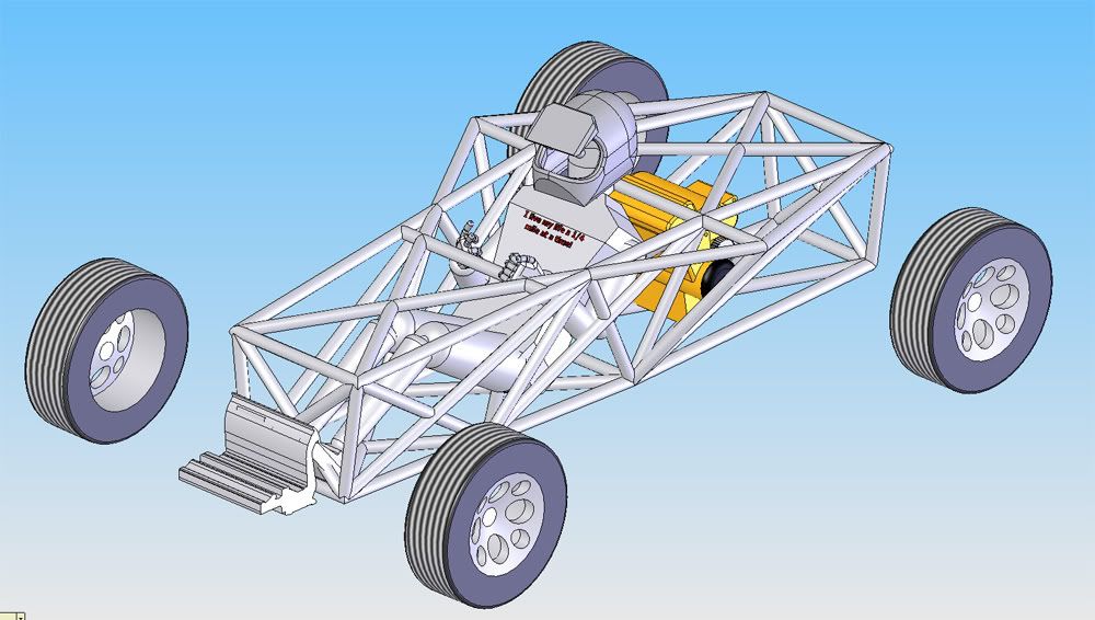
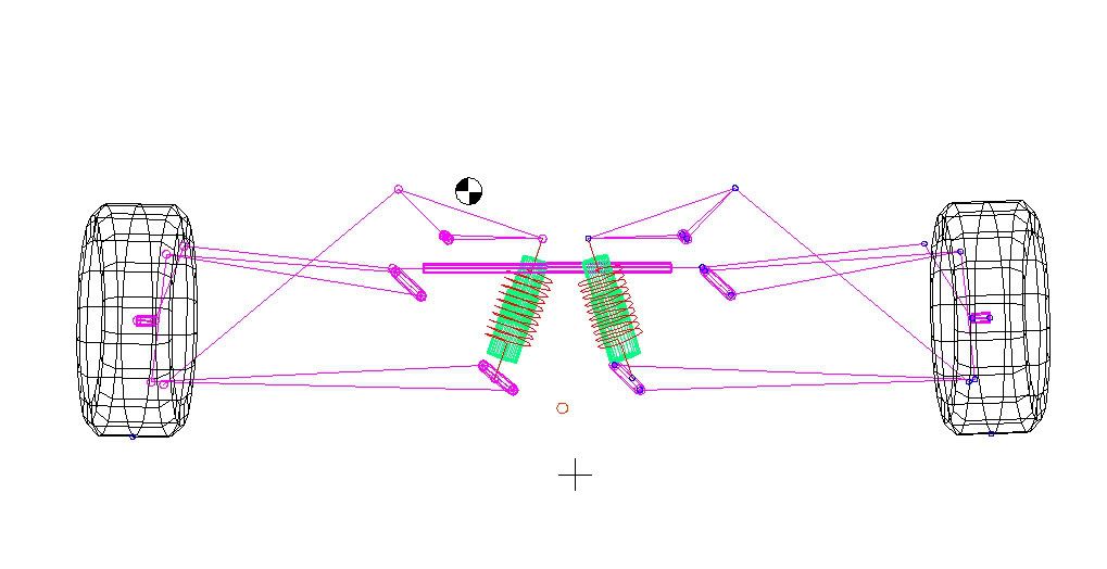
also , you can find usefull models, seats etc. on http://www.3dcontentcentral.com
Suspension front inboard cam:
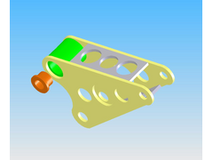

front cam assembly
Rear Cam:
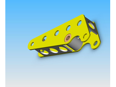

rear cam assembly
Cutaway of front cam spindle:

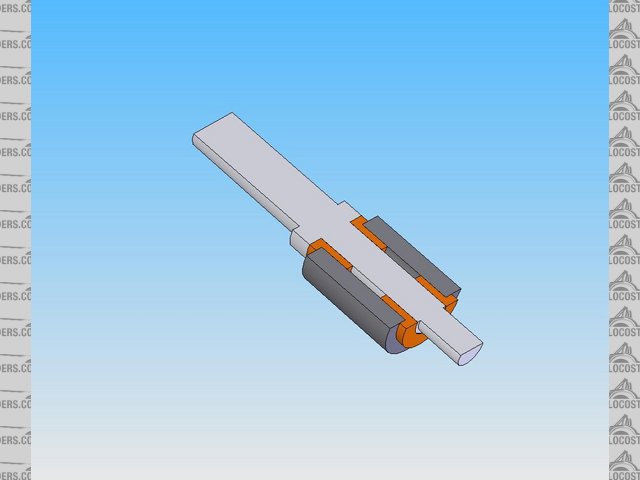
Front spindle
The bushes will be oilites and a grease nipple will be mated to the cam assembly.
These 3 pictures show how useful solidworks is.
I have modelled the suspension to find the optimum angle to mount my wishbones to the chassis.
I need un-equal wishbones that will rest with the bottom of the car at 60-75mm from the road and raise another 75mm with my air suspension without
increasing camber too drastically. The will be camber change but it is kept within acceptable limits. It took a few top wishbone changes to get this
right but you can see from the model that camber gain is not excessive.
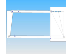

wishbone test level
[img][/img]
[img][/img]
[Edited on 17/2/2007 by nitram38]
Why have you chosen to have little or no camber gain?
quote:
Originally posted by Mad Dave
Why have you chosen to have little or no camber gain?
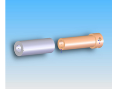

Sorry I showed the wrong chassis point version. Here is what I will use as a general layout for the rear (only a pivot model) The square plate is only
for inboard suspension location.
[img][/img]
Because of the R1 and chain diff, I will have a very narrow rear chassis and very long wishbones:
[img][/img]
with such long wishbones you may find it rolling a lot, which would have a greater effect on camber due to the parallel bones. You would need to make the car quite stiff in roll, either by springs or ARBs. Worth bearing in mind as you continue modelling it!
You might find you have a falling spring rate as it is now
The shocks have "air springs" so just put more air in via the onboard compressor will stiffen them up.
Ride height can be adjusted by the pushrods from the lower wishbone.
The bottom bone will be around 500-550 long.
Camber gain is at a minimum for this set up as I will be able to move the wishbones 3" downwards with minimal gain.
[Edited on 18/2/2007 by nitram38]