andrew.carwithen
|
| posted on 20/3/05 at 06:06 PM |

|
|
FINALLY!!!!
I've finisned the conversion from to discs and LSD!!!! 
This is how I did it:-
Turned down lobro stubshaft to 75mm along its length (cost £10 by local engineering firm) as in attached photo....
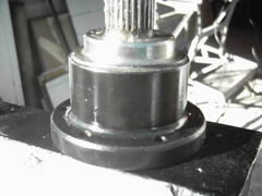 
Rescued attachment p100enginejpg00041.jpg
|
|
|
|
|
andrew.carwithen
|
| posted on 20/3/05 at 06:10 PM |
|
|
...Then I used angle grinder to remove excess weld and protruding ring on inside of rear upright until flush. Trusty powerfile then used to chamfer
inside edge of tube (see attached photo)....
 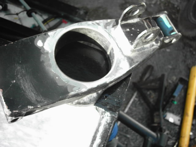
Rescued attachment p100enginejpg00040.jpg
|
|
|
andrew.carwithen
|
| posted on 20/3/05 at 06:13 PM |
|
|
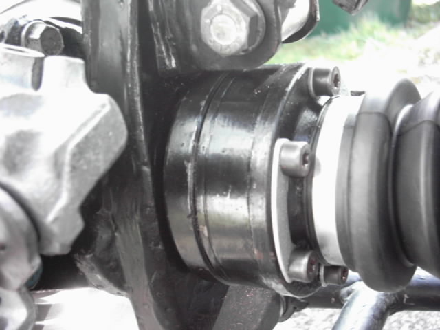
...Uprights were then swapped from one side to another to enable callipers to be fitted. (photo shows clearance which now exhists between stubshaft
and upright)..
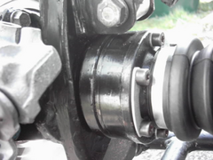 
Rescued attachment p100enginejpg00042.jpg
|
|
|
andrew.carwithen
|
| posted on 20/3/05 at 06:14 PM |
|
|
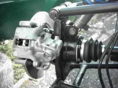
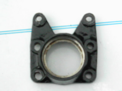
...pic of L/H rear hub assy..
Rescued attachment p100enginejpg00043.jpg
|
|
|
andrew.carwithen
|
| posted on 20/3/05 at 06:16 PM |
|
|
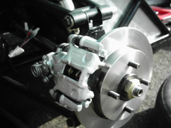
..pic of R/H disc and calliper..
Rescued attachment p100enginejpg00044.jpg
|
|
|
andrew.carwithen
|
| posted on 20/3/05 at 06:19 PM |
|
|
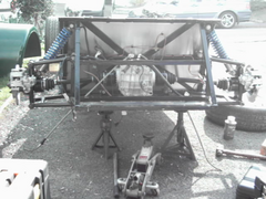
...and finally...pic of complete rear end inc. LSD!..(thanks to Lightning for advice). So it goes to show that it CAN be done with original uprights!
 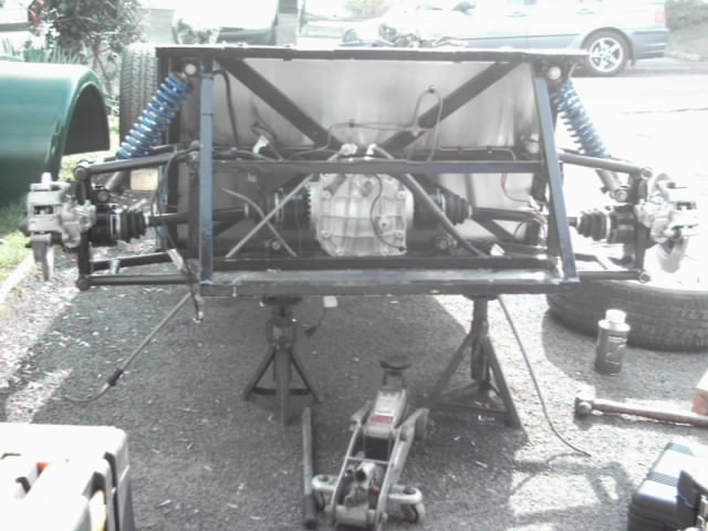
Rescued attachment p100enginejpg00055.jpg
|
|
|
Lightning
|
| posted on 20/3/05 at 06:29 PM |
|
|
Lookin Good
Its about time that you got a move on.
Are you going to put on a bracket on the rear of the diff?
Went out in mine today...bloody cold
[Edited on 20/3/05 by Lightning]
Steve
|
|
|
Northy
|
| posted on 20/3/05 at 06:32 PM |
|
|
Well done Andrew! Beat me to it!
How did you cope with the holes not lining up? 
Graham
Website under construction. Help greatfully received as I don't really know what I'm doing! 
"If a man says something in the woods and there are no women there, is he still wrong?"
Built 2L 8 Valve Vx Powered Avon
|
|
|
Northy
|
| posted on 20/3/05 at 06:33 PM |
|
|
quote:
Originally posted by Lightning
Are you going to put on a bracket on the rear of the diff?
[Edited on 20/3/05 by Lightning]
I've got one on mine, but not sure if I'll re-fit it, is it necessary?
Graham
Website under construction. Help greatfully received as I don't really know what I'm doing!
"If a man says something in the woods and there are no women there, is he still wrong?"
Built 2L 8 Valve Vx Powered Avon
|
|
|
andrew.carwithen
|
| posted on 20/3/05 at 06:59 PM |
|
|
quote:
Originally posted by Northy
Well done Andrew! Beat me to it!
How did you cope with the holes not lining up?
Basically, I found that the two 'lower' holes in the hub carrier would line up with their counterparts in the upright but the two
'upper' holes didn't.
I merely used a round file to elongate both these holes until they did!
Hopefully, (I'm no David Bailey!) the photo will show the holes I had to elongate (the two to the left in pic!)
 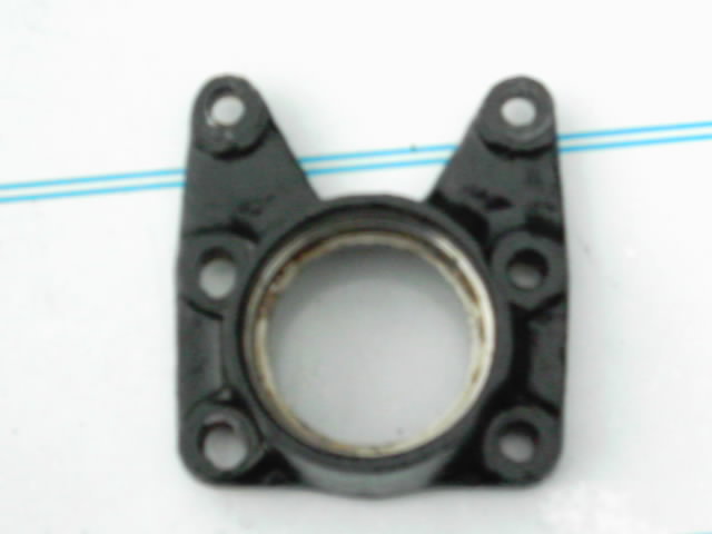
Rescued attachment p100enginejpg00056.jpg
|
|
|
Northy
|
| posted on 20/3/05 at 07:44 PM |
|
|
Andrew,
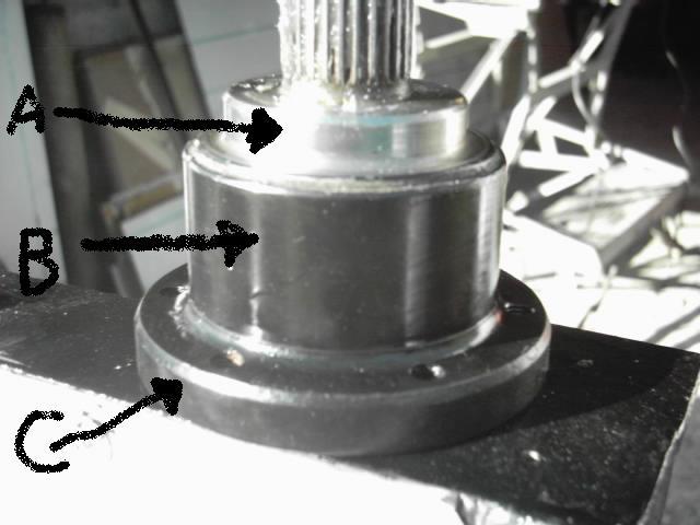
Did you remove material from A & B? What about C?
How much clearance is there now between the edge of C and the back of the upright?
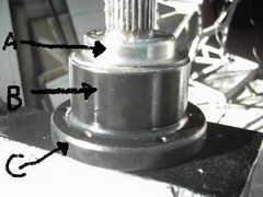 
Rescued attachment untitled.JPG
Graham
Website under construction. Help greatfully received as I don't really know what I'm doing!
"If a man says something in the woods and there are no women there, is he still wrong?"
Built 2L 8 Valve Vx Powered Avon
|
|
|
Northy
|
| posted on 20/3/05 at 07:46 PM |
|
|
What do the teeth (A) actually foul on?
I can't work this out, as B has to go into the upright, and A is much smaller diameter? And it all fitted together on the Sierra!
Graham
Website under construction. Help greatfully received as I don't really know what I'm doing!
"If a man says something in the woods and there are no women there, is he still wrong?"
Built 2L 8 Valve Vx Powered Avon
|
|
|
andrew.carwithen
|
| posted on 20/3/05 at 08:11 PM |
|
|
quote:
Originally posted by Northy
Andrew,
Did you remove material from A & B? What about C?
How much clearance is there now between the edge of C and the back of the upright?
Graham,
'A' is untouched and is as original.
'B' is the area (which included the ABS teeth) I had turned down to 75mm along its length - which is approx. the diameter where
'B' meets 'C' on the original (there's a taper from the ABS teeth end to this shoulder on original. The ABS teeth are
hardened, but a carbide tipped tool soon makes short work of them!)
This allows stubshaft to pass through upright with approx 3-4 mm clearance all round.
Once the excess weld and protruding lip of the ring are ground back flush with the inner face of the upright and the hub bearings tightened, there is
a clearance again of about 3mm between the flange'C' and the upright. This clearance will not change due to the nature of the Sierra hub
bearings being done up so bleedy tight and so will not change!
I also ground a little away from the weld on the underside of the shock mounting bracket on the upright to aid clearance between it and
'C'.
Its worth a try on your uprights, Graham, as it'll save the hassle of having a larger ring welded in instead.
Regards,
Andy.
|
|
|
Northy
|
| posted on 20/3/05 at 08:18 PM |
|
|
Just been to look at a stub axel in the garage, I should have done that first!
Do you just take the teeth off for clearance in the tube then?
Graham
Website under construction. Help greatfully received as I don't really know what I'm doing!
"If a man says something in the woods and there are no women there, is he still wrong?"
Built 2L 8 Valve Vx Powered Avon
|
|
|
andrew.carwithen
|
| posted on 20/3/05 at 08:26 PM |
|
|
quote:
Originally posted by Northy
What do the teeth (A) actually foul on?
I can't work this out, as B has to go into the upright, and A is much smaller diameter? And it all fitted together on the Sierra!
Ah yes,but the Sierra didn't use Tiger uprights!
In theory, the teeth should pass through the upright as they're about 80mm in dia. and (according to the book!) the dia. of the ring in the
upright is 82mm.
BUT...this is assuming that the ring is perfectly central in relation to the four hub carrier holes in the upright! (and when have you known the Tiger
chassis to be that accurate?)
So, the reason for reducing the diameter is to build in a decent 'tolerance' for any inaccuracy in the upright - thus ensuring a good
running clearance.
Andy.
|
|
|
andrew.carwithen
|
| posted on 20/3/05 at 08:31 PM |
|
|
quote:
Originally posted by Northy
Just been to look at a stub axel in the garage, I should have done that first!
Do you just take the teeth off for clearance in the tube then?
...Yep!..that's what I was trying to explain in my last post!
|
|
|
carlgeldard
|
| posted on 21/3/05 at 11:22 AM |
|
|
FAO Graham
Graham
Well what are you going to do now!!! Its sounds to me that there is more work and cost involved in that solution than just welding larger tubes in.
And removing weld metal from a Joint sounds suspect to me "But Im only a qualified welder what do I know".
Sorry I dont mean to offend anybody but weld metal is there for a reason. The last thing anybody wants is to be going around a corner and the upright
fails because the weld metal or reinforcement has been removed, just to save a bit time and effort.
Let me know Graham as I have still to get you some bits of tube today.
Carl
And also Ford must spend millions on research and development only for us to machine material off from what could be a case hardened component that
has been special designed and tested to do a particular job. It also scares me to think that the driveshaft is only 6 to 8 inches from your back and
the petrol tank. You just dont want a component failure. One last thing to think about is you are going to be driving this car harder than MR average
in his old Serria and you will have more power going to the wheels.
[Edited on 21/3/05 by carlgeldard]
|
|
|
andrew.carwithen
|
| posted on 21/3/05 at 09:11 PM |
|
|
Carl,
No offence taken, but its precisely because I'm not a qualified welder, that I modified my uprights in this way, rather than attempt welding in
larger tubes. I reckon if I had done, I would definitely compromise the strength of the upright due to my inept welding.
If the tube is so fundamental to the strength of the upright, why is it not welded around its cicumference to the same degree on the outer face of the
upright? Is it possible that its only purpose is to prevent water ingress into the cavity of the upright?
As regards taking material off the stub shaft, the lobro shafts are far more substantial than the push-in type drive shafts that were fitted. They are
not hardened (apart from the ABS teeth) and are merely cast steel.
The amount of power the shafts will have to transmit will be similar to that of a Sierra (I'm going to fit a Fireblade engine - approx 130bhp )
but through a much lighter vehicle and hence due to having to overcome less inertia to get the vehicle moving I would suggest be subject to less
stress?
I also went down this route because 'Lightning' had done this on his Avon last year and has suffered no detrimental effects since (touch
wood!)
As regards cost, the only outlay was the tenner to have the stubshafts turned down by a local engineering firm.
Regards,
Andy.
|
|
|
DaveFJ
|
| posted on 22/3/05 at 03:08 PM |
|
|
maybe I am missing something - but the 'tube' in my standard rear hubs is actually just a thin strip of metal vary badly tacked (to
overlap) into a circle, from memory I would say it is only about 0.8mm thick. Do I take from opthers posts that their hubs are different to this ?
Dave
"In Support of Help the Heroes" - Always
|
|
|
carlgeldard
|
| posted on 22/3/05 at 05:36 PM |
|
|
Avon Uprights
The one's that I modified had I piece of tube in the middle, that had a wall thickness of 3.2mm. This was welded all the way around on the
outside of the upright and was stitched on the inside of the upright but on the outside face of the tube. (Inside the upright and can only be seen
during manufacture or as I did when cutting up the upright.) I still say that this needs to be welded. What I will do when I modifiy Grahams uprights
is to grind off all the weld as what has been done and subject it to visual and destructive tests and then let you know what I find.
I cannot be fairer than that.
Carl
|
|
|
Northy
|
| posted on 22/3/05 at 06:22 PM |
|
|
quote:
Originally posted by carlgeldard
What I will do when I modifiy Grahams uprights is.......
.......and subject it to visual and destructive tests.......
Carl
Graham
Website under construction. Help greatfully received as I don't really know what I'm doing!
"If a man says something in the woods and there are no women there, is he still wrong?"
Built 2L 8 Valve Vx Powered Avon
|
|
|
Viper
|
| posted on 23/3/05 at 12:21 AM |
|
|
now because i have been away for a while and because i am a lazy bastard i havent bothered to read all of this thread .
but
all the probs i have seen posted about havent affected me at all, why, because i used a doner that didn't have abs and i made my own uprights
because tigers ones are.... well all who know me know what i think of tigers stuff
|
|
|
carlgeldard
|
| posted on 23/3/05 at 08:12 AM |
|
|
Welderman
http://www.fat-pie.com/bfmtrailer.htm
|
|
|
Northy
|
| posted on 26/3/05 at 06:25 PM |
|
|
Thanks again Carl
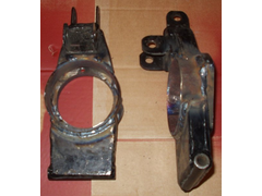 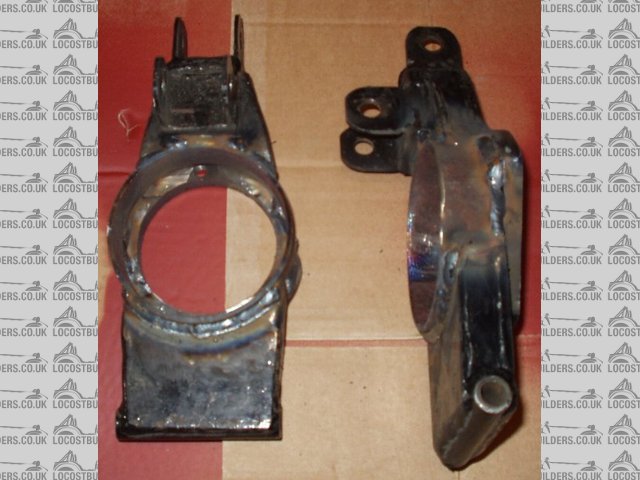
Rescued attachment Modified uprights.jpg
Graham
Website under construction. Help greatfully received as I don't really know what I'm doing!
"If a man says something in the woods and there are no women there, is he still wrong?"
Built 2L 8 Valve Vx Powered Avon
|
|
|
carlgeldard
|
| posted on 26/3/05 at 06:44 PM |
|
|
From that angle it looks like the tube is welder off centre GOOD JOB IT'S NOT!!!! And you could have painted them first.
Carl 
|
|
|