ReMan
|
| posted on 16/1/05 at 10:12 PM |

|
|
Indyblade Propshaft
Am I right in thinking that the propshaft centre bearing mounting, to the footwell/bulkhead plate needs some spacers?
Searched the archive and can`t find anything but got a suspicion i`ve sen or read this somewhere.
Colin
|
|
|
|
|
Hellfire
|
| posted on 16/1/05 at 10:14 PM |
|
|
It does - ours was 28.5mm (3x 3/8"
On our website.... somewhere!
ATB
|
|
|
ReMan
|
| posted on 16/1/05 at 10:24 PM |
|
|
Thanks mate.
Thought i`d seen it on yours too but couldnt find it.
Is that an official MK 28.5 or a best fit 28.5 so each one is different?
What did you make it from, alloy plate or what?
Cheers
|
|
|
Jasalarms
|
| posted on 16/1/05 at 10:32 PM |
|
|
I packed mine out with 3mm alloy untill i got the best angle through the tunnel ( as square as possible in my opinion) 
|
|
|
Jasalarms
|
| posted on 16/1/05 at 10:37 PM |
|
|

|
|
|
ReMan
|
| posted on 16/1/05 at 10:40 PM |
|
|
Thanks all.
I think i`ve got enough to go on now
Colin
|
|
|
Hellfire
|
| posted on 17/1/05 at 09:32 AM |
|
|
quote:
Originally posted by Jasalarms
I packed mine out with 3mm alloy untill i got the best angle through the tunnel ( as square as possible in my opinion)
Apparently you need some angle to relieve stress on the UJ - read it somewhere... someone will comment I'm sure.
|
|
|
ReMan
|
| posted on 17/1/05 at 03:22 PM |
|
|
I thought that the idea was to get as straigty as possible to minimise stress, or is it to minimise vibration?
Help
|
|
|
Hellfire
|
| posted on 17/1/05 at 05:02 PM |
|
|
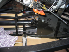
Propshaft Pictures
There you go...


HTH
|
|
|
ReMan
|
| posted on 18/1/05 at 10:21 PM |
|
|
Ta
|
|
|
Avoneer
|
| posted on 19/1/05 at 10:32 PM |
|
|
Won't the ali tunnel panel flex?
Pat...
No trees were killed in the sending of this message.
However a large number of electrons were terribly inconvenienced.
|
|
|
ReMan
|
| posted on 20/1/05 at 12:29 AM |
|
|
S`not ali!
Its solid steel!
|
|
|
Avoneer
|
| posted on 20/1/05 at 04:30 PM |
|
|
Ahhh, is that the curved end of the footwell that comes on the MK chassis?
I've got a book chassis so may be best if I panel the top quarter of the tunnel (drives side) in steel - how thick is the MK stuff and how far
from the end of the diff is the prop joint roughly?
Cheers,
Pat...
No trees were killed in the sending of this message.
However a large number of electrons were terribly inconvenienced.
|
|
|
chrisf
|
| posted on 21/1/05 at 02:30 PM |
|
|
Hellfire:
Did you mount your prop so it is as straight as possible to the engine, then slightly slant it towards the diff?
Or did you kind of average the angles and make the prop straightest overall?
--Chris
|
|
|
J Alderman
|
| posted on 21/1/05 at 03:40 PM |
|
|
The following describes how I installed my prop shaft, which does not vibrate.
If this seems wrong I would be interested to know how is should be done!
I ran the engine & center bearing UJ at 7 degrees with the diff UJ at around 1 degree. The angle I describe is the summation of the angles in the
vertical & horizontal plane
The UJ's must be run at a slight angle, or they will wear out rapidly, I believe 1 degree is required.
The aim of a prop shaft instalation is to equal out all the UJ angles. to avoid "flick" i.e. if the joint on the engine is at 7 degrees
then the second should be 7 degrees.
Having said all this when I looked at the instalation it looked right. I just worked out because I did not want to trust my gut feeling
Hope this is of some help
James
|
|
|
DarrenW
|
| posted on 21/1/05 at 04:18 PM |
|
|
If you dont put a bit of articulation on the bearings you get what is called brinelling. Instead of the balls or rollers rolling correctly in the
raceways they dont move as fast as the raceway and effectively slide. The severity of this could cause a flat spot which will rapidly wear out the
surfaces, cause noise and vibration etc. Excessive articulation will also promote rapid wear in a plain bearing. I have been working on an automotive
project that required 0.4deg of articulation which required a specially designed bearing to cope with it.
|
|
|
ReMan
|
| posted on 21/1/05 at 11:16 PM |
|
|
quote:
Originally posted by Avoneer
Ahhh, is that the curved end of the footwell that comes on the MK chassis?
I've got a book chassis so may be best if I panel the top quarter of the tunnel (drives side) in steel - how thick is the MK stuff and how far
from the end of the diff is the prop joint roughly?
Cheers,
Pat...
Its 3mm steel and about 3ft, notice my dexterity in using both metric and imperial units
|
|
|
Hellfire
|
| posted on 21/1/05 at 11:37 PM |
|
|
quote:
Originally posted by ReMan
quote:
Originally posted by Avoneer
Ahhh, is that the curved end of the footwell that comes on the MK chassis?
I've got a book chassis so may be best if I panel the top quarter of the tunnel (drives side) in steel - how thick is the MK stuff and how far
from the end of the diff is the prop joint roughly?
Cheers,
Pat...
Its 3mm steel and about 3ft, notice my dexterity in using both metric and imperial units
Our's is 1/8" about 925mm... too add to that . We kept the prop as straight as possible from the engine and bisected the angles to give
equal angle before and after the UJ.
|
|
|
Avoneer
|
| posted on 22/1/05 at 12:28 AM |
|
|
Cheers,
So it does bolt to that metal footwell end plate then (just to clarify)
Pat...
No trees were killed in the sending of this message.
However a large number of electrons were terribly inconvenienced.
|
|
|
ReMan
|
| posted on 22/1/05 at 10:46 PM |
|
|
Yes, like Hellfires pics, above.
If I was doing it myself I think i`d like to extend the plates even further down the tunnel, for a bit of added uj protection!
If you want another pic let me know.
www.plusnine.co.uk
|
|
|
Avoneer
|
| posted on 22/1/05 at 11:26 PM |
|
|
Any pics would be great as I am at the finishing stages of my chassis and anything that will help my blade installation before the chassis is blasted
and painted will be great.
Thanks,
Pat..
No trees were killed in the sending of this message.
However a large number of electrons were terribly inconvenienced.
|
|
|
ReMan
|
| posted on 23/1/05 at 10:26 PM |
|
|
See this one and futwell1 in my archive.
As I menrtioned previously, if I was building my own chassis, I might extend the plate even further back down the tunnel to shroud the UJ a bit
more.
 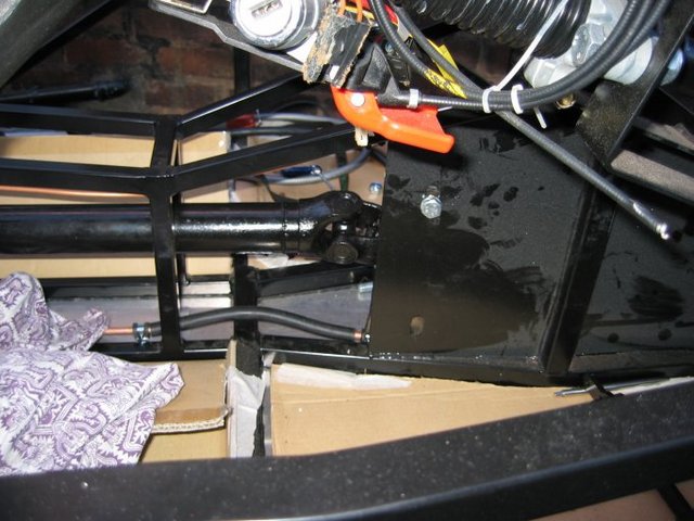
Rescued attachment fwell2.jpg
www.plusnine.co.uk
|
|
|
Avoneer
|
| posted on 23/1/05 at 10:38 PM |
|
|
Cheers.
I'll take my plate all the way back to the upright.
Pat...
No trees were killed in the sending of this message.
However a large number of electrons were terribly inconvenienced.
|
|
|


%20(WinCE).JPG)