Ivan
|
| posted on 28/4/08 at 08:47 PM |

|
|
Part aluminium Chassis
The last two threads on alternate chassis brought to mind an idea I've been kicking around and rather than hijack those threads have decided to
put this out there:
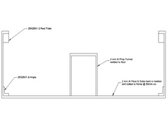
Why not get rid of most of the steel in the cockpit area from the firewall back and replace it with slightly thicker aluminium plate (about 2mm)
bolted to a basic steel frame made of Angle iron that connects to the front and rear steelwork of the original chassis.
The aluminium could be folded and/or welded to make an impressively strong box section.
This is a very basic NTS drawing of what I had in mind
 
Description
|
|
|
|
|
Pulsar
|
| posted on 28/4/08 at 09:14 PM |

|
|
You'd be better off using tube rather than angle. I can't say I'm too keen on the idea of an aluminium transmission tunnel.
That'll require a lot of welding and the heat affected zone may compromise the strength of the floor, which seems to be a bit thin (2mm?) for a
floor panel, really.
|
|
|
Mr Whippy
|
| posted on 28/4/08 at 11:51 PM |

|
|
Remember that aluminium in contact with steel corrodes very quickly especially if road salt gets on it. Just think of all the landys with huge chunks
missing out the body and they are made of quite a good grade. Although aluminium is quite strong it tends to tear very easily in a crash and would
probably do not very well against a production car.
Oh wait till the morgan lot see that  it'll be 'I would like to inform you that you are talking through your a$$ mr whippy, my aero 8
has been bla bla bla...' it'll be 'I would like to inform you that you are talking through your a$$ mr whippy, my aero 8
has been bla bla bla...'
Fame is when your old car is plastered all over the internet
|
|
|
kb58
|
| posted on 29/4/08 at 01:31 PM |

|
|
Aluminum heat-distorts a LOT.
Also, if you build a steel and aluminum chassis, choosing material such that they have the same torsional stiffness - they will weight the SAME! For
this reason there is no point in using aluminum.
The only place aluminum's useful is if the steel ends up too thin to work with. But in terms of torsional resistance-to-weight, the two are the
same.
Mid-engine Locost - http://www.midlana.com
And the book - http://www.lulu.com/shop/kurt-bilinski/midlana/paperback/product-21330662.html
Kimini - a tube-frame, carbon shell, Honda Prelude VTEC mid-engine Mini: http://www.kimini.com
And its book -
http://www.lulu.com/shop/kurt-bilinski/kimini-how-to-design-and-build-a-mid-engine-sports-car-from-scratch/paperback/product-4858803.html
|
|
|
Ivan
|
| posted on 29/4/08 at 04:51 PM |

|
|
All the comments make good points, however to some extent I feel they miss the point to the extent that there are alternative ways of doing the
chassis beyond fibre reinforced alternatives that, if properly engineered, could save weight and gain torsional resistance as the current chassis is
far from optimal.
I think Cymtrix showed the above in his thesis and I just wish I had retained my structural analyses skills of 30 years ago (without weeks of study to
brush up on them) sufficiently to confidently re-analyse the chassis and find the optimum solution between material selection, monocoque and space
frame, cost and ease of building.
In particular the sheet materials used in the "standard" chassis are very badly utilised from a structural point of view and the correct
bonding, thickness selection and frame member sizing could make both a significant difference in weight and torsional strength.
Please don't assume that my proposals are in any way properly engineered as they are just doodles with the above in mind.
Also - bearing in mind Kimini's shout, irrespective of material it is things like moments of inertia etc that affect tortional resistance and
not just material type and weight and that is what needs to be got right.
[Edited on 29/4/08 by Ivan]
|
|
|
vinnievector
|
| posted on 29/4/08 at 09:35 PM |

|
|
Iam thinking more the way of alu and carbon fibre tubing no welds but torsional brackets in two halves as to negate any cracks and to brass bush and
bolt them Some special aircraft fastener called a Hi lock in titanium holding tube to brackets ,gusset plates T70 sheet alclad sides riveted at 2in
intervals should really stiffen this lot up and doubler where need for strength .
|
|
|
Benonymous
|
| posted on 30/4/08 at 12:36 AM |

|
|
Semi Monocoque
I think a better route would be a semi monocoque design. The open ends would have bulkheads fabricated out of square tube. The bulkheads would be
bonded/riveted in place and then the remainder of the front and rear structures could be attached. I wouldn't use angle anywhere I wanted
structural rigidity. It's weak as anything and will fail unpredictably. It would be OK to use as corner reinforcement in this folded metal box
though.

BTW. The proportions are nowhere near what you'd have in a 7 style chassis. This is a quick lashup in SW before anyone pulls me up 
|
|
|
C10CoryM
|
| posted on 30/4/08 at 02:38 AM |

|
|
I would look into backbone frames if you are looking for the lightest aluminum frame. Can make them very stiff w/o any extra weight. Only problem is
driver protection/support is needed and that adds weight. Not like a locost is safe anyhow 
"Our watchword evermore shall be: The Maple Leaf Forever!"
|
|
|
907
|
| posted on 30/4/08 at 10:03 AM |

|
|
The problem with welding Aluminium is... (IMHO)
(I've copy & pasted some of this from an old post of mine.)
When aluminium is manufactured it is cast into large billets.
As it cools and solidifies it forms into crystals that are uniform in shape and size.
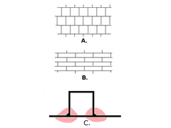
Diagram A below is a simplified version of what might be seen under magnification.
In this state it has a tensile strength of 4 to 6 tons/sq inch. (steel is 25 to 30)
Aluminium is however extremely malleable and can be cold formed into usable shapes,
rolled into sheet, drawn through dies, or drawn over mandrels to form hollow sections.
This stretches and compresses the crystal structure as in diagram B.
This has the effect of greatly increasing the tensile strength, depending on the amount. (Work hardening).
Unfortunately, when we then weld this structure, we locally anneal it and
reform the crystals as in diagram A, and consequently return it back to it's lower tensile strength.
Diagram C shows a welded fabrication similar to the drawing at the start of this thread.
The main structure would be strong, but the pink areas would be weak.
Under load, either constant, but more so alternating, these areas would be prone to failure.
As already stated distortion would be considerable.
So it's glue, bond, rivet or bolt.
Welding this type of structure is a no no.
There are also other issues.
Normally the tunnel needs to be wide at the front to allow for the gearbox.
Fitting of the prop and it's maintenance.
Possible fracture of the prop and protection of the car occupants.
The fitting of a hand brake and it's adjustment.
The running of wires, brake lines, fuel pipes, etc. normally in the tunnel.
The later post/drawing IMHO has issues too.
The huge area of the underside would be unsupported, unless the gap was filled with some sort
of honeycomb structure and riveted/glued in place.
With a double skin it becomes as heavy as a conventional chassis.
Sorry I can't be more positive.
As I've said, it's just my opinion. Feel free to ignore.
Paul G
 
Rescued attachment crystal-structure-2.jpg
|
|
|
kb58
|
| posted on 30/4/08 at 01:49 PM |

|
|
quote:
Originally posted by 907
... The main structure would be strong, but the pink areas would be weak. Under load, either constant, but more so alternating, these areas would be
prone to failure.
Paul G
Really? Since the annealled area is dead-soft, that's the last place I'd expect cracking. I think it would either start at the hard/soft
interface, or more likely, after the overall structure work-hardens and becomes brittle.
Like you said, what gets lost in the challange are all the other issues. What does the 200lb driver+seat attach to? Where do the hoses, wires, brake,
clutch, and shifter assembly go? Where do the seatbelts attach? Once steel cross-tubes are added to handle the above, the need for welding goes away,
as does the entire design exercise. I'm considering using a torque-tube structure in my next design - in steel. For anything subjected to
repetitive bending or a high vibration environment, steel is the way to go. As I ranted before, the stiffness/weight is identical between the two.
What always comes up is, "but race cars are made from aluminum". True, but they: Don't weld aluminum in structural applications,
have a short life, are thrown out once the engineer says so, and employ structural engineers who know the fatique life of stressed aluminum panels
they're designing, much like the airline industry have.
Mid-engine Locost - http://www.midlana.com
And the book - http://www.lulu.com/shop/kurt-bilinski/midlana/paperback/product-21330662.html
Kimini - a tube-frame, carbon shell, Honda Prelude VTEC mid-engine Mini: http://www.kimini.com
And its book -
http://www.lulu.com/shop/kurt-bilinski/kimini-how-to-design-and-build-a-mid-engine-sports-car-from-scratch/paperback/product-4858803.html
|
|
|
C10CoryM
|
| posted on 30/4/08 at 04:41 PM |

|
|
This aluminum chassis seems to be working fine 

Dead sexy, light weight, used in a production car, lots of miles on them and they even crash well.
"Our watchword evermore shall be: The Maple Leaf Forever!"
|
|
|
vinnievector
|
| posted on 30/4/08 at 04:42 PM |

|
|
Tensile
Yes ,the only way you could sort out this problem is to heat treat or salt bath the hole chassis back down to T,0 state and retreat to a tensile state
again say T70
there are some treatment charts on line but you would need a large oven or a large salt bath...
|
|
|
kb58
|
| posted on 30/4/08 at 07:11 PM |

|
|
quote:
Originally posted by C10CoryM
This aluminum chassis seems to be working fine... Dead sexy, light weight, used in a production car, lots of miles on them and they even crash well.
Right... so what specs will be used to heat-treat your frame? To what spec will it be tempered? What loads are being fed into the chassis? At what
rate? What vibration frequencies and amplitudes? What is the resulting estimated time to failure for this frame? Answer all these question accurately
and yes, building an aluminum chassis is safe and easy. Don't know the answers? No problem, make everything three times as thick and it'll
work fine, nevermind weight as much - or more - than the steel equivalant.
[Edited on 4/30/08 by kb58]
Mid-engine Locost - http://www.midlana.com
And the book - http://www.lulu.com/shop/kurt-bilinski/midlana/paperback/product-21330662.html
Kimini - a tube-frame, carbon shell, Honda Prelude VTEC mid-engine Mini: http://www.kimini.com
And its book -
http://www.lulu.com/shop/kurt-bilinski/kimini-how-to-design-and-build-a-mid-engine-sports-car-from-scratch/paperback/product-4858803.html
|
|
|
907
|
| posted on 30/4/08 at 07:58 PM |

|
|
quote:
Originally posted by kb58
quote:
Originally posted by 907
... The main structure would be strong, but the pink areas would be weak. Under load, either constant, but more so alternating, these areas would be
prone to failure.
Paul G
Really? Since the annealled area is dead-soft, that's the last place I'd expect cracking. I think it would either start at the hard/soft
interface, or more likely, after the overall structure work-hardens and becomes brittle.
Like you said, what gets lost in the challange are all the other issues. What does the 200lb driver+seat attach to? Where do the hoses, wires, brake,
clutch, and shifter assembly go? Where do the seatbelts attach? Once steel cross-tubes are added to handle the above, the need for welding goes away,
as does the entire design exercise. I'm considering using a torque-tube structure in my next design - in steel. For anything subjected to
repetitive bending or a high vibration environment, steel is the way to go. As I ranted before, the stiffness/weight is identical between the two.
What always comes up is, "but race cars are made from aluminum". True, but they: Don't weld aluminum in structural applications, have a
short life, are thrown out once the engineer says so, and employ structural engineers who know the fatique life of stressed aluminum panels
they're designing, much like the airline industry have.
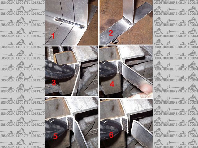
Out of curiosity I did a workshop test today.
A 1/4" fillet in 1/16" sheet aluminium (pure) with 5% silicon filler.
Cut off the stop/starts and placed in the vice so that I tested just one leg.
By the look and feel, the soft area was about 3/4" wide and the amount of bend 20deg forward and the same back.
After 3 cycles I could feel more resistance in the HAZ and 2 cycles later it broke.
I conclude that where the toe of the weld meets the flat sheet is a stress raiser and this is why it tends to be the weak point.
I don't pretend that my test was in any way scientific. I did it as I said, to satisfy curiosity.
Paul G
 
Rescued attachment Weld-fracture-s.jpg
|
|
|
Benonymous
|
| posted on 1/5/08 at 01:40 AM |

|
|
Well done Paul! Nice to see a bit of practical investigation into a problem. I'm not at all surprised that the weld failed where it did.
To the thread starter. Get the "race and Rally Car Source Book" . It's one of the standard works for scratch chassis constructors
and covers the semi monocoque and full monococque designs.
Lots of photos and illustrations will help you decide on the way forward.
|
|
|
C10CoryM
|
| posted on 1/5/08 at 04:55 AM |

|
|
quote:
Originally posted by kb58
Right... so what specs will be used to heat-treat your frame? To what spec will it be tempered? What loads are being fed into the chassis? At what
rate? What vibration frequencies and amplitudes? What is the resulting estimated time to failure for this frame?
[Edited on 4/30/08 by kb58]
No idea. Ask the GM engineers. Just posting an example of an aluminum frame which is working very well in the real world as a production car. $120k
and you can have your own to play with.
Yes, it is hydroformed so they have obviously put thought to where the material needs to be thicker. Interesting note though is that apparantly
the aluminum frame is exactly the same dimensions as the steel one.
"Our watchword evermore shall be: The Maple Leaf Forever!"
|
|
|
Ivan
|
| posted on 1/5/08 at 07:10 AM |

|
|
Well I guess from the above that you need an experienced materials and design engineer to design a really lightweight but amateur buildable
chassis.
However I suspect that the really significant weight gains are to be found in the engine & gearbox (BEC  ), propshaft & diff, driveshafts,
suspension arms, uprights, brakes, wheels and tyres. Also, these are the ones that most probably have the biggest influence on performance (both
speed, handling and comfort) so matter the most. ), propshaft & diff, driveshafts,
suspension arms, uprights, brakes, wheels and tyres. Also, these are the ones that most probably have the biggest influence on performance (both
speed, handling and comfort) so matter the most.
Time for some of you real engineers out there to apply your minds to this and come up with an affordable and achievable solution. 
|
|
|


