Jesus-Ninja
|
| posted on 4/2/08 at 11:07 AM |

|
|
more thinning tubing or less thicker tubing
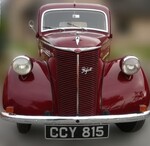
I'm in the depths of chassis design, and being able to see the light at the end of the tunnel, I started drafting some overlays for the body
work on top of the chassis.
As things turn out, I have capacity for a larger frame under the shell, so here's my question.
Should I make a bigger frame?
Clearly, if I simply make the triangles bigger, with the same size tubes, it will be weaker - more prone to bending in the elements.
So I could go for a bigger frame, with more structure in it, but that would add weight.
So I'm thinking - could I put in more structure, but go for, say, 19mm primaries with 12mm secondaries?
It needs to be strong, as it will have circa 350BHP running through it. Whilst weight is always a concern, particularly in the chassis where
it's nigh on impossible to remove it later, this has never been inteneded to be a mega-light 500kg vehicle. 800kgs will be fine.
[Edited on 4/2/08 by Jesus-Ninja]
Suspension geometry tool here >>> http://www.locostbuilders.co.uk/viewthread.php?tid=81376
|
|
|
|
|
Mr Whippy
|
| posted on 4/2/08 at 11:33 AM |
|
|
personally if the frame was similar to the 7's I would prefer to increase the thickness of the rails that make up the sides of the passenger
compartment in case of a T-bone accident. This is the area the 7 is most deficient in.
[Edited on 4/2/08 by Mr Whippy]
Fame is when your old car is plastered all over the internet
|
|
|
smart51
|
| posted on 4/2/08 at 11:34 AM |
|
|
I'd look at thinner wall tubes rather than smaller diameter. Do you actually need the chassis to fill the bodywork? Is there any advantage?
No and No? Leave it.
|
|
|
Jesus-Ninja
|
| posted on 4/2/08 at 12:00 PM |
|
|
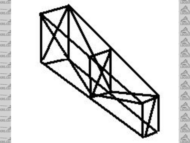
If you look at the design attached, I think there is capacity for the upper engine bay rail to run up to the bend in the cage, at the base of the
windscreen. Would this not improve rigidity?.jpg)
Suspension geometry tool here >>> http://www.locostbuilders.co.uk/viewthread.php?tid=81376
|
|
|
Mr Whippy
|
| posted on 4/2/08 at 12:30 PM |
|
|
Perhaps the tubes rearranged as below in orange would enhance the strength
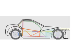 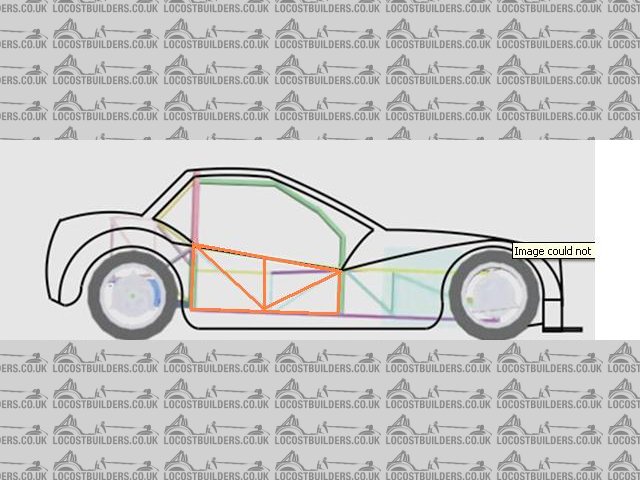
Rescued attachment car.JPG
Fame is when your old car is plastered all over the internet
|
|
|
Mr Whippy
|
| posted on 4/2/08 at 12:38 PM |
|
|
also I think I remember that this was quite a wide car, so one thing you could do is make the sides into trusses like this particularly dreadful
sketch. Doing that would make the car a lot stiffer and safer in a side impact.
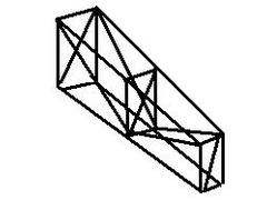 
Rescued attachment truss.JPG
Fame is when your old car is plastered all over the internet
|
|
|
Doug68
|
| posted on 4/2/08 at 12:55 PM |
|
|
To quote Peter Elleray: "As regards the overall level of stiffness, it is an order of magnitude higher than the roll stiffness of the
suspension, which is usually a good rule of thumb to work to
" from here
The more effective cross sectional area you take up in in the chassis the stiffer it will be.
So I'd advise using all the space under the frame to get the thing as stiff as you can.
As a side note it'll be safer too as you can get seated further in from the frame, so it has to crush more before you start getting crushed.
If you look at Fred W B's car he's effectively used side pods to gain substantial frame stiffness. He's got the numbers somewhere I
believe it was a good improvement over without them on.
http://www.locostbuilders.co.uk/photos.php?action=showphoto&photo=sf%20proto%20canamsa%20side%20pod.jpg
http://www.locostbuilders.co.uk/photos.php?action=showphoto&photo=sf%20proto%20canamsa%20torsion%20test.jpg
[Edited on 4/2/08 by Doug68]
[Edited on 4/2/08 by Doug68]
Doug. 1TG
Sports Car Builders WA
|
|
|
Mr Whippy
|
| posted on 4/2/08 at 12:59 PM |
|
|
what ever you doing it ain't working as i still can't see those pictures  
oh that's better, cool chassis. Kind of what I was going on about but better
[Edited on 4/2/08 by Mr Whippy]
Fame is when your old car is plastered all over the internet
|
|
|
Doug68
|
| posted on 4/2/08 at 01:00 PM |
|
|
fecking feck feck fecking thing. 
Doug. 1TG
Sports Car Builders WA
|
|
|
Jesus-Ninja
|
| posted on 4/2/08 at 01:51 PM |
|
|
quote:
Originally posted by Mr Whippy
Perhaps the tubes rearranged as below in orange would enhance the strength
LOL, oddly enough, they already do! They were obscured by the ouline of the body work. What you could see was actually the tunnel inside.
Great minds, eh?!
Yes, I've read about side pods increasing rigidty. A couple of things I have also considered:
1) The upper and lower chassis in the engine bay are of course connectde with upright elements and then trianglulated. There is a rectanular shape in
the bottom as well, which the engine sits in. I'd thought about joining this also to the upper engine bay, and to the outer lowers. The engine
bay would then have 3d triangular sides, rather than 2d. If that makes sense!
2) The other is that the body is wider than the chassis. The bosy will need support along the sides with what I can only describe as a shelf. The stop
the self drooping when people inevitably lean on it, it will need support between the outer lip and the lower body. This would also add strength in
the way that side pods do. (the plan of the body should explain a little better...)
[Edited on 4/2/08 by Jesus-Ninja].jpg)
Suspension geometry tool here >>> http://www.locostbuilders.co.uk/viewthread.php?tid=81376
|
|
|
RazMan
|
| posted on 4/2/08 at 04:52 PM |
|
|
My chassis has extra side rails to improve stiffness and offer a little more side impact protection.
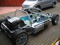 
Rescued attachment Rolling Chassis.jpg
Cheers,
Raz
When thinking outside the box doesn't work any more, it's time to build a new box
|
|
|
Jesus-Ninja
|
| posted on 4/2/08 at 05:00 PM |
|
|
quote:
Originally posted by RazMan
My chassis has extra side rails to improve stiffness and offer a little more side impact protection.
Ahhhh!! Excellent! That's exactly what I am looking at doing!
Of course, the question is do I use the same tube as the main chassis, something lighter, or can I even go with less on the main "inner"
chassis, due to the stiffness introduced by the extra structure?
Suspension geometry tool here >>> http://www.locostbuilders.co.uk/viewthread.php?tid=81376
|
|
|