andyps
|
| posted on 9/1/06 at 02:00 PM |

|
|
Revised chassis for suspension mounts
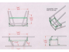
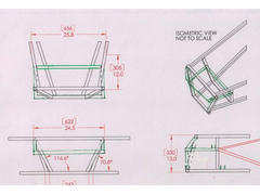
I am planning inboard front suspension by rocker wishbone arm, and trying to ensure my suspension pick up points are in the right place. For the
rockers to work I need to have the top mountings pointing upwards. The pictures below show my thoughts about how to fabricate suitable mountings - can
anyone see a problem? Thanks to Jim McSorley for the original drawing.
Will be using MK Indy wishbones and Sierra uprights if it makes a difference.
 
Rescued attachment chassis front.jpg
Andy
An expert is someone who knows more and more about less and less
|
|
|
|
|
andyps
|
| posted on 9/1/06 at 04:55 PM |

|
|
Wow - 133 people have looked and no replies. Does that means it is perfect or so bad that everyone is lost for words!!
Andy
An expert is someone who knows more and more about less and less
|
|
|
ned
|
| posted on 9/1/06 at 04:58 PM |

|
|
looks ok to me, check that the nose cone will be wide enough at the front where the tubes have been moved. should be ok, but i'd certainly check
anyway.
looking at it it'd make more sense to run a horizontal member from half way up the fu tube forward to the front assembly. even if it was skewed
inwards, as longas there was a flat surface to weld your pickup to and it was braced if it overhuing the tube that'd save a lot of jigged and
frame work and weight of all that other tube.
There is a design about for a rocker system with the rockers mounted above the chassis and the shocks inthe middle, have you seen it?
Ned.
try this: http://www.locostbuilders.co.uk/upload/inboard.JPG
the red bits are additional chassis members required, the blue bits are where the shocks go and the black bits are push rods/wishbones.
artistic license, all rights reserved 
[Edited on 9/1/06 by ned]
beware, I've got yellow skin
|
|
|
andyps
|
| posted on 9/1/06 at 05:00 PM |

|
|
I think the nose cone and/or the side panel may need some alteration as the rectangle of tube which the top mounts will fit on is as wide as the top
cross member at the front.
Ned - a picture would help.
Andy
An expert is someone who knows more and more about less and less
|
|
|
Piledhigher
|
| posted on 9/1/06 at 08:26 PM |

|
|
Andy,
Take a look at my picture archive to see how I attempted what you are trying to do.
Cory
|
|
|
britishtrident
|
| posted on 9/1/06 at 08:26 PM |

|
|
You are meaning simple rocker arms as on the Lotus GP cars of the 60s and 70s ? or push rod suspension
--- both tricky to engineer properly because of the big chassis loads.
|
|
|
andyps
|
| posted on 9/1/06 at 09:49 PM |

|
|
Cory - that is probably how I will end up, but having already built the basic chassis frame roughly according to the book I am adding the frame into
it, and may end up junking the rest, or leaving it - depends what it looks like and how it all fits together!!
Britishtrident - not sure quite what the Lotus GP cars of the 60s and 70s were like but probably - I am meaning a wishbone that extends inside the car
to produce a rocker rather than a push (or pull) rod.
I do understand about the loads - by adding in the extra frame, and leaving the original I should have something pretty strong. I have studied the
Raw/Sylva Stryker and am building at least as strong as that appears to be - and it seems to work pretty well.
Andy
An expert is someone who knows more and more about less and less
|
|
|
britishtrident
|
| posted on 9/1/06 at 11:33 PM |

|
|
Do a google search on Lotus 25 or 33 these had that type of wishbone as did the 49
Pretty sure you will need to use proper bearings on the pivots rather than bushes --- needle rollers would be easy Metros are a potential source as
are 60s/70s/80s jags.
A few issues involved -- to late at night to go into in detail right now.
|
|
|
Liam
|
| posted on 9/1/06 at 11:58 PM |

|
|
I'd have some more triangles in there personally. This area wants to be both stiff and strong with the loads you will put into it. At the very
least consider this: high loads on your rocking arm pivots will want to bend the chassis up at the front. This will put big bending loads on those
rear verticals because your horizontals (that your top brackets attach to) feed right into the middle of them. At the very least it ought to be
doubled up to 1"x2" to make it stiffer in that direction, but better to be triangulated from behind.
Additional triangulation throughout the front suspension box would be beneficial too.
Liam
[Edited on 9/1/06 by Liam]
 
Rescued attachment chassisfront.JPG
|
|
|
andyps
|
| posted on 10/1/06 at 11:56 AM |

|
|
Liam,
I do plan to add more triangulation - the pictures I used don't show it - thanks for the input though about the triangulation behind the bar - I
will certainly incorporate that, with some additional bracing between top and bottom bones. I am working on the principle that the area the bones are
attached to needs to be as strong as possible.
Britishtrident - the Striker only uses two poly bushes (one on each end of a long tube) where I plan to use four as I will be making a regular bone
with extensions. Do you think it really needs roller bearings given the relatively light weight?
Andy
An expert is someone who knows more and more about less and less
|
|
|
britishtrident
|
| posted on 10/1/06 at 04:15 PM |

|
|
Using off the shelf top wishbones and modding them isn't really on -- also the mountings also need to be really stiff hence poly bushes
aren't a good idea.
|
|
|
andyps
|
| posted on 10/1/06 at 06:06 PM |

|
|
I will be custom making the bones - just using the MK ones for now to get the mountings in the right place and as a pattern for one half of the bone.
Andy
An expert is someone who knows more and more about less and less
|
|
|


