cymtriks
|
| posted on 10/2/03 at 09:42 PM |

|
|
accurate front suspension
After reading the thread about fixing the suspension mounts accurately in position I thought I'd share my ideas. I've posted them as a new thread as
the original seems to have changed subject half way along.
I'm considering several ways of doing this. Three of them are described below.
The jigs in all cases positions the mounts on both sides of the car at once to ensure that things line up side to side as well as front to back and
top to bottom.
1) Avoid drilling any holes untill the brackets are welded in position. Blue the sides of the brackets and use a jig to scribe a mark to position a
centre punch. I can think of several ways to do this. However the jig would be tricky and trying to accurately centre punch and drill in situ may also
be tricky. There may not be enough room to get a drill in straight.
2) Fix the brackets to a jig using the pre drilled holes in their relative positions. As there are so many diffent surfaces to weld up at different
angles it's hard to see this being easy in practice.
3) Make assembly L (tubes LA, LB, LC, LD) complete with undrilled brackets. Mark, centre punch and drill before fixing to the car. Bolt a jig to the
front mounts and use this to position the remaining brackets. Exactly how hard that last jig would be to make I've no idea.
Can anyone think of a really good order in which to mark, drill and assemble so ensuring everything lines up well?
|
|
|
|
|
Mark Allanson
|
| posted on 10/2/03 at 11:06 PM |
|
|
Surely its the position of the holes is the important bit, I used the holes in the brackets as the starting point, any inaccuracies of the brackets,
or any slight distortion of the chassis due to welding is dialled out using the jig. It ensures perfect alignment of the wishbones once fitted no
matter what the brackets are mounted to.
The accuracy of the fabricated wishbones is a different matter, 1mm inaccuracy is equal to about .33degrees of castor, but shimming the wisbones with
1mm washers in oversize brackets gives a level of correction to (hopefully) give precise alignment.
Hope the image gives my ramblings some clarity
 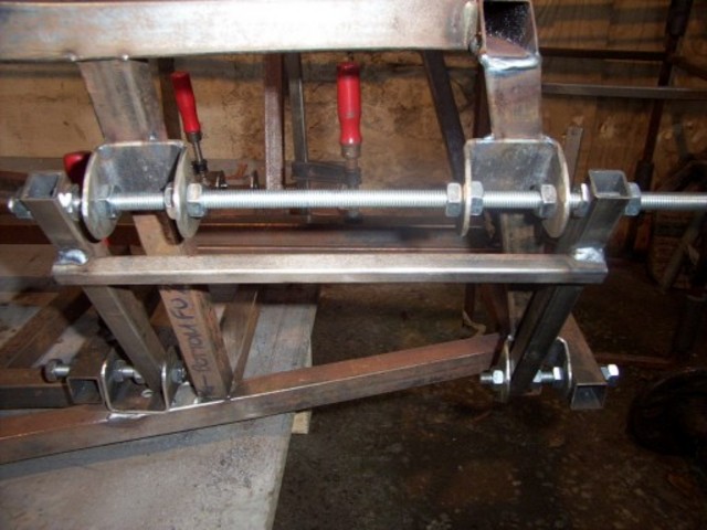
Rescued attachment DCP_0324sml.jpg
|
|
|
robinbastd
|
| posted on 10/2/03 at 11:18 PM |
|
|
Mark,can I borrow that jig sometime?
When you gather the troops to build up your car,as mentioned elsewhere,I'll gladly pitch in- even if it just to keep the tea flowing!
regards
Ian
|
|
|
Mark Allanson
|
| posted on 10/2/03 at 11:23 PM |
|
|
No probs, I think I will give it a coat of paint, its getting a little rusty in the barn. Hopefully a lot more lads in the area will start building
and we can sort a bit of a support group
Anyone building or not in Cornwall, give us a post
Mark
|
|
|
robinbastd
|
| posted on 10/2/03 at 11:31 PM |
|
|
Well,I spoke to a chap today who is the owner of an unbuilt RobbyNudd Exmo (best left that way too-I have got one!) and have tried to persuade him
not to buy a W***hatever,and to go the MK route. Think I might have sold his Exmo as well,all I need to do is sell mine now!
|
|
|
Hornet
|
| posted on 11/2/03 at 09:08 PM |
|
|
Mark.. I used a jig after seeing yours.. big thanks
I have a question though.. on the attached file my dimensions used have placed the upper brackets differently from yours.. mine are almost off LA and
LB
Can you see where i am going wrong? Or can anyone?

|
|
|
Mark Allanson
|
| posted on 11/2/03 at 10:45 PM |
|
|
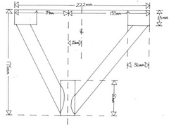
Image of my original (rough working!) CAD drawing (Can anyone teach me TurnipCad?)
I set the rear lower mounts to be exactly the height of an M10 Nylock nut plus 3 threads away from the F*ck You tubes(I will cut the bolts to suit),
the hole centres exactly 25mm above the chassis lower members. it works out that the upper rear mounts rear edge coincides with the rear edge of the
FU's plus the thickness of the bracket. You will probably have to read this 8 times before it makes any sense. The upper forward brackets fall exactly
right on the L tubes with the lower forward corner coinciding with the forward leading edge of LA.
I will add another reply with an image to make sense of this.. I think you will need it!!
 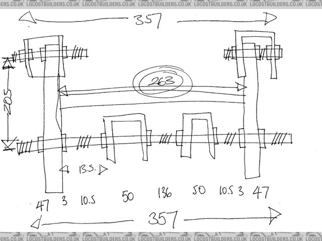
Rescued attachment Jig Layout Dimensions.jpg
|
|
|
Mark Allanson
|
| posted on 11/2/03 at 11:00 PM |
|
|
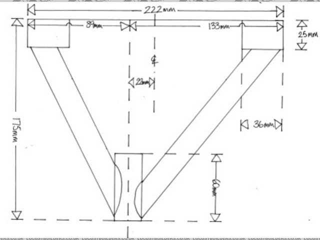
Sorry about the massive image, another coming up, I think it clarifies the verbal garbage of the last post.
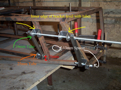 
Rescued attachment JigDimsImage.jpg
|
|
|
kb58
|
| posted on 12/2/03 at 03:28 AM |
|
|
I keep telling you guys how to make it perfect. You build the suspension from the arms, *inward.* Basically you make a jig which holds the rod ends
in space with the correct vertical, horizontal, and depth offsets. Now you KNOW it is correct. You then set this jig up right next to the chassis,
and simply build mounting ears out to the rod ends. Put a bolt through the rod ends when you tack weld the brackets and bingo, perfectly located
brackets.
This method is even more effective if you wait until *after* you finish welding the entire chassis, because it will distort, sometimes to a
frightening degree. After it's all welded up, bent like a pretzel or not, THEN weld on the suspension tabs with the jig. Only this way will you
absolutely know they are correct.
[Edited on 12/2/03 by kb58]
|
|
|
scutter
|
| posted on 12/2/03 at 09:55 AM |
|
|
Boys, If you want accreate mesurement look up "front suspension dimensions simplified for your build! " in Merlins photo archive.
Many people can testify that these are correct myself included.
Dan.
|
|
|
Hornet
|
| posted on 12/2/03 at 11:26 AM |
|
|
regarding merlins plans
Scutter... tx for advice but.... if you look at merlins diag the dimensions are incorrect. (No offence Merlin) for example
343 between bottom brackets.. but if you add 25.87 + 307 + 25.87 = 358.74 then remove the 3mm from each braket and you are left with 352.74.. not
343.
I would say it shoud be 21mm from the end (which equates to 36mm wide brackets)
So i am still confused .. or totally wrong??
|
|
|
Mark Allanson
|
| posted on 12/2/03 at 09:31 PM |
|
|
Just twigged what is going on, you are building the castor into the brackets whereas the castor is developed by using the asymetric upper wishbone.
The brackets should be evenly spaced about the centreline looking from the side - this is why your brackets are not centering properly
|
|
|
Mark Allanson
|
| posted on 12/2/03 at 10:07 PM |
|
|
Try these dimensions for size, you got me worried for a few minutes, if loads of people have offset their upper brackets to the rear of the car, and
used offset upper wishbones, they will have 11 degrees of castor (self centring enough to snap your wrists)
 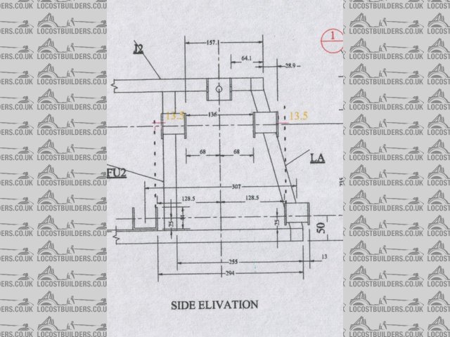
Rescued attachment SideViewBrackets.jpg
|
|
|
davef
|
| posted on 13/2/03 at 07:59 AM |
|
|
Hi Mark davef here i would just like to clear things up for other people reading this site. if you position the suspension brackets centrally over the
suspension chassis uprights la lb assuming you have made the front according to book 75mm kickback, then you will have no castor angle. the top
wishbone if made to book does not give enough offset to give you 5.30 degrees. the only way to get 5.30 degrees is to move the brackets toward the
rear of the car. and the only way to set the castor is with a protractor either with a dummy mandril between the ball joint swivel holes or like i
said in the other thread put two set screws in the caliper holes and place the protractor against the screws and move the top brackets untill you have
attained the correct 5.30 degrees, while maintaining the correct centers between top and bottom brackets. cheers davef.
|
|
|
Hornet
|
| posted on 13/2/03 at 08:54 AM |
|
|
soz Mark.. but i have used cad to create castor... and my dimensions are correct. I basically used 5.3 as my starting point at the centre line of the
bottom wishbone and drew the rest so that I could make my jig. I am 100% confident my drawing produces 5.3 degrees castor.
Note the 2nd drawing you have uploaded shows an overhang at the front of the chassis by 13mm (Which i dont see on your picture) which results in the
dimension in my drawing with the question mark being 63.5mm and not 70.5mm just to confuse things more!! but there is no vertical size for upper
brackets so it means nothing 
Hope we can clear this up.. as i have stopped build..
PS.. DaveF has been saying LA and LB is wrong for ages now... What does Ron say??????

|
|
|
davef
|
 posted on 13/2/03 at 11:40 AM posted on 13/2/03 at 11:40 AM |
|
|
Hi Hornet & Mark just to try and explain a little further, the top wishbone drg on page 83 is a little confusing yes it is asymmetrical it gives 222mm
overall from the left it gives 102mm to threaded boss from the right it gives 121mm this gives a difference of 19mm which is supposed to pre set your
castor near enough,NO IT DONT. Half of 222mm is 111mm minus 102mm =9mm offset which is not enough to set your castor if you place the top front
bracket central on LA LB. for a quick check on the castor scribe a line at 5.5 degrees with a plastic protractor from the corner of an A4 sheet
measure along the line a distance of 225mm which is the ball joint ctrs on a cortina upright mark off and measure across from this mark and you will
see that the distance is 21mm this is the distance the top ball joint should be behind the bottom ball joint when mounted on the car in order to give
you 5.3 degrees if a person looks down on their finished car and the top ball does,nt appear to be behind the bottom one ,believe me its wrong. cheers
davef
|
|
|
Mark Allanson
|
| posted on 13/2/03 at 07:11 PM |
|
|
Ron champion, what a twat!!
|
|
|
Mark Allanson
|
| posted on 13/2/03 at 08:42 PM |
|
|
After sticking pins ina effigy of RC, got the calculator out and did a few sums (should it before plugging in the MIG really!)
The 9mm asymetry of the upper wishbone will give me 2.29 degrees of castor (SIN castor=9/225). To get 5.5 degrees I need a total of 21.56mm
(SIN5.5/225=21.56)
To maintain the strength of the brackets on the tube (1, I dont want the brackets hanging off the tubes 2,I dont really want to move them), I have to
gain 12.56mm
I am going to make my own wishbones, the ones on the car are S/H ones give to me by Tim (Thanks Tim!), and a a bit dubious in the quality and accuracy
department.
Can anyone see any reason why I cannot make the bottom wishbones asymetrical as well? And if this is a valid idea, should I make the offsets the same
or bias it to the upper or the lower?
If I do have to move the brackets, there is enough adjustment in my jig to do this, but I would rather not put a hacksaw to my hard work!!
Did someone say that RC's locost company went bust? Wonder why - twat!!
|
|
|
davef
|
| posted on 14/2/03 at 06:34 AM |
|
|
Hi Mark believe me i was as upset as you when i discovered this error, i could,nt figure out if it was the chassis or the wishbone, i think what
possibley happened is the person who did the drg of the wishbone got it wrong, because at first glance it appears to give you the +-20mm required, i
think it has fooled quite a lot of people including me. but having said that it,s a lot easier to alter the chassis than make new wishbones. best of
luck in the future davef.
|
|
|
Mark Allanson
|
| posted on 14/2/03 at 09:50 PM |
|
|
As the bracket look right on the chassis, (not looking like they are going for a walk cos they are bored!), and that I need to make my wishbone
anyway, can anyone see any problems with making the upper wishbones like this?
Rescued attachment AltWishboneSML.jpg
|
|
|
Hornet
|
| posted on 14/2/03 at 11:35 PM |
|
|
I assume you have got sizes correct m8.. so only question i would ask is.. Is there enough clearance for shock and coil?

|
|
|
Rorty
|
| posted on 15/2/03 at 02:32 AM |
|
|
It's obvious something will have to be altered to achieve the correct degree of caster.
If it were me, I would be locating the wishbone brackets as centrally as possible on their respective chassis members to reduce any overhang. I've
seen similar scenarios, where the overhanging brackets have failed due to stresses caused by resonnance in the chassis.
If Mark Allanson's redesigned wishbone accomodates the coilover and provides full clearance at full lock etc, then I would have thought a re-draw of
the wishbone jig would be the simplest, most effective approach.
The best solution would be to make the brackets from RHS, so they actually wrap part-way around the chassis members, thus providing a mor secure
purchase. If that's done, then it would also be possible to make the brackets wider, which would allow for shimming the wishbones fore and aft, to
alter the castor.
Shims could be either AN washers, or simply accurately cut washers from sheet steel of a known thickness, using a tank
cutter.
Cheers, Rorty.
"Faster than a speeding Pullet".
PLEASE DON'T U2U ME IF YOU WANT A QUICK RESPONSE. TRY EMAILING ME INSTEAD!
|
|
|
jcduroc
|
| posted on 26/2/03 at 11:35 PM |
|
|
Accurate chassis (w/ jig)
Rorty, Cymtricks
After reading all the posts on this subject I wonder if the really "accurate" thing to do wouldn't be to build a complete jig whose measurements
were dictated by the suspensions.
As I am in the process of designing my own chassis (not by the book(s)) intended to accomodate:
a) Double wishbone IRS w/ standard 1600 Sierra diff+half-shafts; this means a rear track=1530-2xrear wheel offset (or +2x rear wheel inset).
b) Front Double wishbone susp w/ Cortina Mk3 spindles/hubs/disc brakes/calipers to a front track >= rear track.
My idea, ATM (please comment), is to build a jig that:
1. Primaraly locates the hubs;
2. Provides a "floor" for the chassis at the intended ride height;
3. Will remain valuable until the wheels are mounted and setting the susps (caster, toe, camber).
I imagine Rorty would be delighted to design this jig; am I wrong?
João
|
|
|
Rorty
|
| posted on 27/2/03 at 04:09 AM |
|
|
Joao, The method of chassis building you describe, is exactly the way many professional race car builders do it. There are even commercial jigs
available for such purposes.
I'm one of those lucky people who has the ability to visualise the final product, and I'm quite happy building a chassis in "space".
There are still a lot of high-end factories though, that still do it the time honoured way with a chassis jig. It makes sense to use one for
production runs too, of course.
If you wanted to go that route, it requires a little more work initally (making the jig), but the end result is a Mechano style of assembley, with
pinpoint accuracy.
I would be surprised if people like MK and Leugo don't have such a jig. It means they can employ people with basic skills to do all the
fabrication/assembley and still have an accurate end product.
Before I start receiving litigeous mail, I'm in no way infering MK or Leugo actually employ anything but the highest skilled individuals!

I would be happy to draw up a suitable jig. Did you envisage one just for yourself, or were you thinking along the lines that others could benefit
from it too? The reason I ask is, if it were for general usage, then it would be best if it were designed to accomodate all the common permutations of
hubs/axles/track widths/wheelbases etc. to suit everyones tastes. If you're interested in taking it further, perhaps you should start a new thread,
titled "Chassis jig", or whatever.

Cheers, Rorty.
"Faster than a speeding Pullet".
PLEASE DON'T U2U ME IF YOU WANT A QUICK RESPONSE. TRY EMAILING ME INSTEAD!
|
|
|
jcduroc
|
| posted on 27/2/03 at 11:18 PM |
|
|
quote:
Originally posted by Rorty
Joao, The method of chassis building you describe, is exactly the way many professional race car builders do it...If you wanted to go that route, it
requires a little more work initally (making the jig), but the end result is a Mechano style of assembley, with pinpoint
accuracy...
I would be happy to draw up a suitable jig. Did you envisage one just for yourself, or were you thinking along the lines that others could benefit
from it too? The reason I ask is, if it were for general usage, then it would be best if it were designed to accomodate all the common permutations of
hubs/axles/track widths/wheelbases etc. to suit everyones tastes. If you're interested in taking it further, perhaps you should start a new
thread, titled "Chassis jig", or whatever.
Rorty
I think I'll start a new thread on this subject.
I'm very happy that my way of forseeing the construction of a "Locost Seven-inspired 2-seater roadster" is shared and I definitely
intend to do it this way. If you can help me on drawing a suitable jig I'll even happier; as you put it it should be suitable for the MOST
COMMON PERMUTATIONS of both front and rear susp geometries.
After this msg I'll start the thread "CHASIS JIG"
Cheers
João
I've started the jig construction for my next build(s ???).
From the current one it is evident that without a decent jig everything come out of the expected / desired tolerance.
[Edited on 15/7/04 by jcduroc]
JCM
|
|
|


