ned
|
| posted on 10/1/05 at 02:49 PM |

|
|
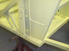
chassis infill panels
quick question, why are the infill panels round the trailing arms/driver/passenger seat sides welded in steel and not just ally?
Is it a strength issue for the trailing arms? is it meant ot give that chassis member more rigidity/support?
The chassis is triangulated all the way down the side of the cockpit/engine bay and my chassis is also triangulated across the floor like a caterham
race chassis.
Do I still need to do these infill panels out of steel or could I leave them out and just rivet them with the ally side panels later on?
cheers all,
Ned.
beware, I've got yellow skin
|
|
|
|
|
locoboy
|
| posted on 10/1/05 at 03:27 PM |

|
|
good question Ned, my chassis came with one welded in and one missing lol
i want to take the existing one out and replace with ally.
Seeing as im not doing a live axle build if it is a trailing arm issue it wont matter.
ATB
Locoboy
|
|
|
britishtrident
|
| posted on 10/1/05 at 03:44 PM |

|
|
In a true spaceframe no member should be subject to bending loads all the loads should be fed in at nodes where tubes join -- on a real world
spaceframe chassis it dosent work that way we have to accept that some brackets will have to be mounted on members but they should be as close to
nodes as as possible.
The chassis members in question M1 and M2 are subject to beam loading and high sheer loads, the upper trailng arm brackets in particular are near the
centre of M1 & M2 -- this is not a good idea. The original early Lotus 7 chassis had the top links mounted in a\similar location and the
chassis member in question cracked with alarming regularity.
Also consider what happens from a personal safety point of view if the weld on a trailling link or its bracket bracket fails.
[Edited on 10/1/05 by britishtrident]
[Edited on 10/1/05 by britishtrident]
|
|
|
Stu16v
|
| posted on 10/1/05 at 06:31 PM |

|
|
I agree with the above, put steel in. Alos, consider gusseting the trailing arm brackets if they overhang the tubes. I didn't, and 18 months of
abuse has started to crack the steel plate where the brackets are welded to it...
Live axle Westys have no steel in-fill or gussets, but this point is a known weak area on hard driven and/or big power motors. I thought I would get
away with the gusset thing, what with the steel plates, and dedion (Because the dedion tube isn't transmitting any twisting loads into the
chassis via the trailing arms like a live axle does, the diff does that bit instead).
HTH Stu.
Dont just build it.....make it!
|
|
|
MikeRJ
|
| posted on 10/1/05 at 07:25 PM |

|
|
quote:
Originally posted by Stu16v
(Because the dedion tube isn't transmitting any twisting loads into the chassis via the trailing arms like a live axle does, the diff does that
bit instead).
Until you put the brakes on 
This area is also used for seat belt mountings, so a reasonable margin of overengineering isn't a bad idea!
[Edited on 10/1/05 by MikeRJ]
|
|
|
ned
|
| posted on 10/1/05 at 07:36 PM |

|
|
fair points being made, guess I'll have to get the hacksaw back out...
Ned.
|
|
|
Stu16v
|
| posted on 10/1/05 at 08:05 PM |

|
|
quote:
Until you put the brakes on 
Fair point...unless you have inboard brakes too 
Dont just build it.....make it!
|
|
|
Mark Allanson
|
| posted on 10/1/05 at 09:16 PM |

|
|
....(Because the dedion tube isn't transmitting any twisting loads into the chassis via the trailing arms like a live axle does, the diff does
that bit instead)
I am a little confused as normal,
The way I see it, all the force making the car go forward is generated at the tyres, which are fastened to the dedion tube, which has its only
connection to the chassis by the trailing arms. As you accellerate, the full load of the engine is fed into the chassis by the lower trailing arm in
compression and the upper one in tension, and vice versa on braking. The diff has to resist the twisting force of the prop and the driveshafts.
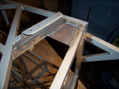
I made my trailing arm mounts the strongest part of the car, over engineered perhaps. I could not see how 257mm of 25x25mm ERW could handle the load
over a period of time, and there have been several failures of the chassis brackets the hold the trailing arms.
Are there any engineers out there who can confirm my thinking, or should I stop trying to design stuff and stick to welding stuff together?
 
Rescued attachment Rear brackets.jpg
If you can keep you head, whilst all others around you are losing theirs, you are not fully aware of the situation
|
|
|
Rorty
|
| posted on 11/1/05 at 02:02 AM |

|
|
It does seem like a weak point as stock.
Mark, lovely job (as always), but I don't see where you've braced yours. A piece of flat bar, the same length as the mount, welded from
the front outside corner of your mount, at 45 degrees, back in to the corner of the vertical tube would brace it and strengthen it a lot.
Cheers, Rorty.
"Faster than a speeding Pullet".
PLEASE DON'T U2U ME IF YOU WANT A QUICK RESPONSE. TRY EMAILING ME INSTEAD!
|
|
|
ned
|
| posted on 11/1/05 at 10:27 AM |

|
|
rorty,
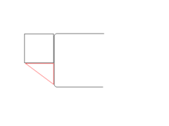
you mean like this? this is how i'm planing on bracing mine:
ps aerial cross section view, not to scale 
[Edited on 11/1/05 by ned]
 
Rescued attachment bracket.gif
beware, I've got yellow skin
|
|
|
Rorty
|
| posted on 11/1/05 at 12:24 PM |

|
|
That's it Ned, but you only need to use a length of flat bar to fill the long side of your red triangle.
Cheers, Rorty.
"Faster than a speeding Pullet".
PLEASE DON'T U2U ME IF YOU WANT A QUICK RESPONSE. TRY EMAILING ME INSTEAD!
|
|
|
MikeRJ
|
| posted on 11/1/05 at 08:21 PM |

|
|
quote:
Originally posted by Mark Allanson
I am a little confused as normal,
The way I see it, all the force making the car go forward is generated at the tyres, which are fastened to the dedion tube, which has its only
connection to the chassis by the trailing arms. As you accellerate, the full load of the engine is fed into the chassis by the lower trailing arm in
compression and the upper one in tension, and vice versa on braking. The diff has to resist the twisting force of the prop and the driveshafts.
This would be the case with a standard live axle where the trailing arms have to resist the torque reaction of the diff. However, on a de-dion axle,
the diff is bolted directly to the chassis, so any loading of the trailing arms is purely compressive or tensile on acceleration or overrun
respectively. With standard outboard brakes, you will still get the normal torque reaction fed into the trailing arms, i.e. lower one in
tension,upper one in (somewhat less) compression. As Stu says, inboard brakes would get rid of this, as well as providing unsprung weight
benefits.
Irrespective, I think you are wise to have strengthened this area up as you have. The consequences of trailing arm brackets snapping don't bear
thinking about., and the standard design certainly does look a little marginal to me.
Whilst we're off the topic, does anyone know if an inboard conversion for the Seira rear drivetrain has ever been attempted?
|
|
|
Mark Allanson
|
| posted on 11/1/05 at 08:47 PM |

|
|
quote:
Originally posted by Rorty
It does seem like a weak point as stock.
Mark, lovely job (as always), but I don't see where you've braced yours. A piece of flat bar, the same length as the mount, welded from the
front outside corner of your mount, at 45 degrees, back in to the corner of the vertical tube would brace it and strengthen it a lot.
The bracket is made in one piece, instead of 2 separate 2" brackets. This (I think) will be enough to overcome the bracket cracking senario. Its
the brace to the chassis which I was trying to show. The bracket now extend s right up to the top rail, so the M upright is effectively 3" deep
and 3mm with the standard 25x25x1.6mm in its normal position, all welded as one piece
 
Rescued attachment Rear brackets2.jpg
If you can keep you head, whilst all others around you are losing theirs, you are not fully aware of the situation
|
|
|
Rorty
|
| posted on 11/1/05 at 09:12 PM |

|
|
Got it!
Cheers, Rorty.
"Faster than a speeding Pullet".
PLEASE DON'T U2U ME IF YOU WANT A QUICK RESPONSE. TRY EMAILING ME INSTEAD!
|
|
|
Aloupol
|
| posted on 11/1/05 at 11:27 PM |

|
|
quote:
Originally posted by MikeRJ
quote:
Originally posted by Mark Allanson
I am a little confused as normal,
The way I see it, all the force making the car go forward is generated at the tyres, which are fastened to the dedion tube, which has its only
connection to the chassis by the trailing arms. As you accellerate, the full load of the engine is fed into the chassis by the lower trailing arm in
compression and the upper one in tension, and vice versa on braking. The diff has to resist the twisting force of the prop and the driveshafts.
This would be the case with a standard live axle where the trailing arms have to resist the torque reaction of the diff. However, on a de-dion axle,
the diff is bolted directly to the chassis, so any loading of the trailing arms is purely compressive or tensile on acceleration or overrun
respectively. With standard outboard brakes, you will still get the normal torque reaction fed into the trailing arms, i.e. lower one in
tension,upper one in (somewhat less) compression. As Stu says, inboard brakes would get rid of this, as well as providing unsprung weight
benefits.
Irrespective, I think you are wise to have strengthened this area up as you have. The consequences of trailing arm brackets snapping don't bear
thinking about., and the standard design certainly does look a little marginal to me.
Whilst we're off the topic, does anyone know if an inboard conversion for the Seira rear drivetrain has ever been attempted?
I agree with Mark.
What stops the wheel from going ahead without the car when accelerating? The trailing arms via the De Dion tube.
Where does the motoring force acts? At tyre contact patch.
The reactions in the trailing arms are IMHO the same for De Dion or live axle.
It's a bit late in the evening to sort it but I even think that the torque doesn't act on the diff's bolts in case of Sierra sprung
diff. (As long as the diff's bearings are not seized  ) )
[Edited on 11/1/05 by Aloupol]
|
|
|
kaymar
|
| posted on 12/1/05 at 12:02 PM |

|
|
hey mark great welding i know the dax rush has a very similar bracket to yours but strangely the transmision tunnel is not as robust as
the book chassis
|
|
|
MikeRJ
|
| posted on 12/1/05 at 01:32 PM |

|
|
quote:
Originally posted by Aloupol
I agree with Mark.
What stops the wheel from going ahead without the car when accelerating? The trailing arms via the De Dion tube.
Where does the motoring force acts? At tyre contact patch.
The reactions in the trailing arms are IMHO the same for De Dion or live axle.
It's a bit late in the evening to sort it but I even think that the torque doesn't act on the diff's bolts in case of Sierra sprung
diff. (As long as the diff's bearings are not seized  ) )
I think you hvae some slightly confused thinking. The bolts that hold the diff to the frame MUST resist the torque reaction of the porpshaft and
driveshafts, there is simply thing else to stop the differential spinning around and tying everything in knots. This is really the only area where
the de-dion and live axle are fundamentaly different.
The Force to push the car forwards does go through the trailing arms, that was never in doubt. However, the thrust is applied by the stub axle /cv
joint and through the wheel bearing, which happens to be in the middle of the two trailing arms, hence both arms will be in compression. There will
be a very small torque applied to the hub simply due to the drag of the wheel bearing, but this is going to be negligible.
|
|
|
Stu16v
|
| posted on 12/1/05 at 06:43 PM |

|
|
As Mike says...
To help you picture it, as drive is taken up, the diff pinion will naturally want to try and 'climb' up the crownwheel, which in turn try
and turn the diff about the driveshaft axis.
Dont underestimate how much force needs to be transmitted here either...
Dont just build it.....make it!
|
|
|
Aloupol
|
| posted on 12/1/05 at 06:52 PM |

|
|
This turned me around during the day and my conclusion is... You are right.
For my defence: it was 2:30 in the night when I wrote this yesterday... 
The torque acts on the diff and the thrust acts on the suspension.
|
|
|
Peteff
|
| posted on 12/1/05 at 08:17 PM |

|
|
Is this force there all the time?
Does it act more when setting off from a standstill and decrease once the car is in motion?
yours, Pete
I went into the RSPCA office the other day. It was so small you could hardly swing a cat in there.
|
|
|
JoelP
|
| posted on 12/1/05 at 08:23 PM |

|
|
yes
it does, smarty pants... proportional to the weight of your right foot. proportional to the weight of your right foot.
|
|
|


