chrisf
|
| posted on 5/5/04 at 01:25 PM |

|
|
IRS Box Support
Hi all. I'm looking for advice on how to support my IRS box. Usually, I suspect that verticle bending load are transfered to the shock towers.
However I'm using inboard damper.
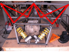
I'm looking at two ideas. You can see in the pictures that the first idea is to weld 1/2 or 3/4" DOM from the corner of the IRS box to the
corner of what will be the chassis tower.
The second idea is to fabricate a large, fully-gusseted 'X' out of 1/2" or 3/4".065 DOM. The 'X' will the bolt to the
shock tower and the IRS box. If this will work, it may be a better solution as I can access the dampers easier.
Any thoughs are appeciated.
--Chris
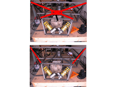 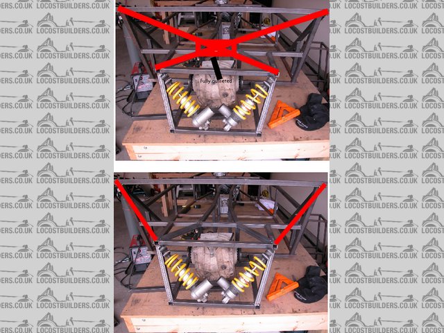
Rescued attachment SupportTogether.jpg
|
|
|
|
|
britishtrident
|
| posted on 5/5/04 at 01:40 PM |
|
|
I don't think you have to involve the book shock towers at all, you should be able to transfer the loads to the chassis backbone and cockpit
side rails. and the key will be to triangulate the box as best a you can while leaving room for the drive shafts.
The chassis member below the diff where the shocks mount is going to take pretty massive loads also --- perhaps you could use a thick alloy or steel
plate bolted on to te back of the IRS box to stiffen
|
|
|
chrisf
|
| posted on 5/5/04 at 01:52 PM |
|
|
lling a cross brace out of 6061. That way, it is removeable. I'll probably end up duplicating the supports on the top of the box.
|
|
|
pbura
|
| posted on 5/5/04 at 02:17 PM |
|
|
How about mounting the shocks on a plate on top of the diff (after removing present top tubes)?
I would also X brace the bottom of the diff cage, run tubes from the rear four corners of the diff cage to the sides, and maybe have a bolt-on plate,
or bracing tubes, on the back of the diff cage.
Pete
|
|
|
phelpsa
|
| posted on 5/5/04 at 02:24 PM |
|
|
I have been planning on doing what is in the second picture.
Adam
|
|
|
stephen_gusterson
|
| posted on 5/5/04 at 02:41 PM |
|
|
Im no expert, but I would have thought the X version (first pic) would be subject to twisting due to the 'pivot point' formed by the
'x', even with the gusseting
atb
steve
[Edited on 5/5/04 by stephen_gusterson]
|
|
|
Mark Allanson
|
| posted on 5/5/04 at 06:10 PM |
|
|
From a welders perspective (I'm not a designer), you cannot have triangulation without triangles.
The diff is going to try to transmit about 130ftlbs of torque into that frame so you have to channel it somewhere strong, I think you would also have
to beef up the lower rear panel to take the forces
 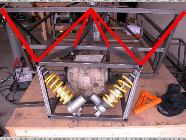
Rescued attachment Triangulation.jpg
If you can keep you head, whilst all others around you are losing theirs, you are not fully aware of the situation
|
|
|
Mark Allanson
|
| posted on 5/5/04 at 06:18 PM |
|
|
or for even more power handling, connet up A and B to produce an immensly strong node at A
 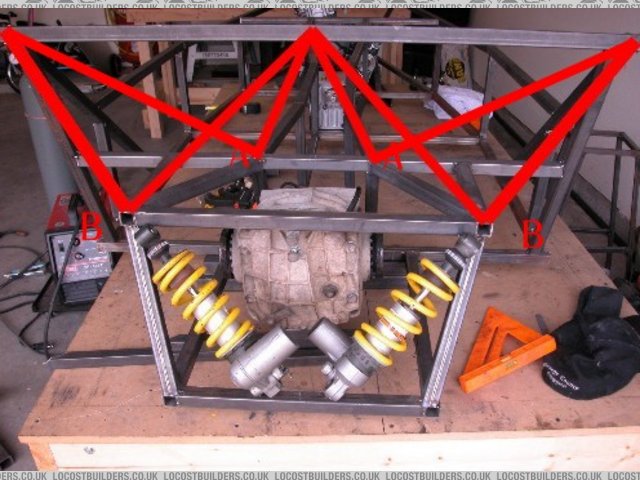
Rescued attachment Triangulation2.jpg
If you can keep you head, whilst all others around you are losing theirs, you are not fully aware of the situation
|
|
|
jcduroc
|
| posted on 5/5/04 at 10:29 PM |
|
|
Rear IRS bay
IMVHO forget the chassis tower.
1) Firstly think of where you're going to anchor your upper & lower wishbones.
2) Secondly consider a strong node for the attachement of your shocks. (Personally I wouldn't place them like that!)
3) Direct loads towards the tunnel and the chassis sides. (That straight ahead tube from the rear to the cockpit bulkhead - which I erased - does
nothing)
4) Excuse the s..tty drawing but I'm really a mess-up with PSP...
Cheers
João
Rescued attachment Rrbay.gif
JCM
|
|
|
locost_bryan
|
| posted on 6/5/04 at 02:35 AM |
|
|
I suspect you will need to triangulate, a bit like the Aussie mods around the front suspension. 
Don't know what arrangement you are using for the shocks (pushrod/rocker?), but would suggest moving the shockers inboard or outboard of the IRS
box to allow "proper" triangulation.
I assume the longitudinal tubes are for the wishbone pickups?
Bryan Miller
Auckland NZ
Bruce McLaren - "Where's my F1 car?"
John Cooper - "In that rack of tubes, son"
|
|
|
britishtrident
|
| posted on 6/5/04 at 06:00 AM |
|
|
quote:
Originally posted by jcduroc
IMVHO forget the chassis tower.
1) Firstly think of where you're going to anchor your upper & lower wishbones.
2) Secondly consider a strong node for the attachement of your shocks. (Personally I wouldn't place them like that!)
3) Direct loads towards the tunnel and the chassis sides. (That straight ahead tube from the rear to the cockpit bulkhead - which I erased - does
nothing)
4) Excuse the s..tty drawing but I'm really a mess-up with PSP...
Cheers
João
|
|
|
britishtrident
|
| posted on 6/5/04 at 06:11 AM |
|
|
quote:
Originally posted by jcduroc
IMVHO forget the chassis tower.
1) Firstly think of where you're going to anchor your upper & lower wishbones.
2) Secondly consider a strong node for the attachement of your shocks. (Personally I wouldn't place them like that!)
3) Direct loads towards the tunnel and the chassis sides. (That straight ahead tube from the rear to the cockpit bulkhead - which I erased - does
nothing)
4) Excuse the s..tty drawing but I'm really a mess-up with PSP...
Cheers
João
A 5 star explanation -- I think what some of the others are missing is that the forces with the largest magnatude have to be contained within the box
of tubes around the diff.
The shock towers are there because the book car needed them -- they are just cantilevered on to the core structure not particularly stiff.
As Joa spotted the damper reactions are going to a totally unsupported tube.
The other big forces are the the loads at the bell crank and the cornering+braking reactions at the lower wishbone pivots. Put enough triangulation in
the diff box with the nodes as close as possible to the spring-damper, bell crank and wishbone mounting points and the jobs done.
|
|
|
MikeRJ
|
| posted on 6/5/04 at 08:05 AM |
|
|
I have simmilar style IRS construction on my chassis, although I'm not going to use inboard dampers. The structure that João sumbitted, whilst
undoubtedly strong, looks a little impractical to me as the outer tubes running from the back of the differential "box" forwards to the
outside of the main chassis would prevent attaching the wishbones to the diff box. (unless I've missed something obvious).
|
|
|
stephen_gusterson
|
| posted on 6/5/04 at 09:26 AM |
|
|
This is when some one should say that IRS doesnt provide huge increases in grip over a std live axle set up, is a lot harder to implement, and easy to
get crap geometry, cos suspension issues are a specialist minefiled.
So I have 
atb
steve
[Edited on 6/5/04 by stephen_gusterson]
|
|
|
Bob C
|
| posted on 6/5/04 at 09:32 AM |
|
|
The shock towers is where the torsional stiffness of the book chassis all leads to - IRS with inboard shocks has to somehow connect this to the
"box", whilst allowing wishbones to move up & down and not breaking due to hitting potholes and allowing access so the diff can be
fitted/ removed and the fuel tank and leave some boot space (OTT I know) while not putting in a ton of metal. Tricky...
IRS with outboard shocks is much easier, suspension loads go where they're supposed to and there is zero vertical stress on the top bone
(precious little on the bottom one either) just "pothole" stresses to worry about. BTW diff torque countered easily by a diagonal in the
sides of the transmission tunnel + it's peanuts compared to suspension loads!
There must be builders who've completed their IRS systems with tales to tell - any photos of the much maligned avon or such? Anybody had any
bits bend in service??????
Cheers
Bob C
|
|
|
Peteff
|
| posted on 6/5/04 at 09:46 AM |
|
|
Use a de dion, it's so much simpler and it's got to be lighter than all the scaffolding you are putting in there. What are the dampers you
have? The massive blob on the bottom looks like it will get in the way. The diff cage looks too wide, your top wishbones will be short and cause
problems. Don't cause yourself problems just to be different, try it the easy way first then get creative.
yours, Pete
I went into the RSPCA office the other day. It was so small you could hardly swing a cat in there.
|
|
|
pbura
|
| posted on 6/5/04 at 12:16 PM |
|
|
Chris,
If you were to remove the diff, which way would you go? Out the bottom or out the back?
I've also been wondering whether it would be possible to mount each shock vertically inside the top tube, and mounted to the bottom tube, just
behind the axle shaft.
Pete
|
|
|
chrisf
|
| posted on 6/5/04 at 01:29 PM |
|
|
Hi all. Thanks for all the responses. Ive gotten quite a few good ideas. The first of which is that the X brace with gussets was a horrible idea. As
to the diff box, I should have stated that the box pictured was in an incomplete state. The R1 dampers are located there in the picture for idea
purposes. After hashing it out, I will mount the dampers to the top of the diff box. A bellcrank system will be used to activate the damper.
Basically, a big triangle will be used: one corner attached to the top of the damper, one to a pickup between the upper A arm and the other to the far
corner of the A arm, near the upright.
The diff box itself is very strong and rigid. There will be two braces from the lower trans tunnel to the lower corners of the diff box, and this will
help stiffen even more. Do this will make getting the diff in and out of the box more difficult, but doable. I will have to tilt the diff sideways and
shove it in from behind. I will fabricate a removable sheet of Ti or Ali for the rear of the box. This should stiffen things up quite a bit.
I could design a DeDion, but then again, I might as well use a live axle. Yes, I under stand their differences. But I chose to use an IRS. Once can
argue the merits of IRS:Live axle/DeDion, but as far as IRS goes, this is the best Ive seen. I just need to solve the box support problem.
Those big lumps on the bottom of the dampers are a remote reservoir. Penskes and such usually have a stainless braided tube that goes from the
reservoir to the damper; mine is attached. The dampers are double adjustable for bump and rebound.
Since this discussion started, Ive looked at a few IRS designs from builders such as Westfield and MK. Though perhaps not the ideal (I certainly like
the cars!), they get away with much less than the modifications suggested here. In the end, I may use some of the suggested modifications, but think
BobC may have distilled it the best, just a simple support to the tower!
--Chris
|
|
|
ned
|
| posted on 6/5/04 at 01:47 PM |
|
|
remember to allow enough space for the fuel tank with any supports you're putting in for the dif cage. I was going to do something similar to
what you are trying,, but decided to go with a dedion axle in the end, £150 its a simple drop in option!
Ned.
beware, I've got yellow skin
|
|
|
Bob C
|
| posted on 6/5/04 at 02:37 PM |
|
|
If you use bellcrank with dampers atop the box, going across, you will have the bellcrank hinge just where the top wishbone hinge is. So use that.
Alternatively make the top bone into a rocker & attatch the dampers to that, simpler and may stress more predictably - your call! Be interesting
to see your final solution!
Bob C
|
|
|
chrisf
|
| posted on 6/5/04 at 02:58 PM |
|
|
Weve chatted on this topic offline before. My reasoning for a separate mount is for adjustability purposes. If I use rod ends, I can make small
changes to adjust the motion ratio, thus changing the spring/dampning rate. Im still trying to design the smaller details in my mind, and some of the
design depends of the upper rear wishbone designwhich is still being finalizedJ.
I wanted to finish fabricating the rear before I got on with the rear suspension, thus the original post.
|
|
|
crbrlfrost
|
| posted on 6/5/04 at 03:42 PM |
|
|
I was just curious why people thinks the torsional loads should be fed to the shock towers. The primary torsional component to the chassis is the
transmission tunnel, not the side walls. Not to mention one of the shock tower tubes is placed in bending and the rear bulhead isn't exactly the
best triangulated structure. I think as well that the best way to impliment an IRS with inboard shocks is to attach directly to the rear tunnel as
well. I've sheeted mine in by bonding aluminium to three sides and triangulating as well as I could on the other two. Frankly, I wouldn't
trust the book shock towers under serious racing as the shocks can transmit some of the largest suspension loads of all.
|
|
|
stephen_gusterson
|
| posted on 6/5/04 at 03:47 PM |
|
|
I fully welded 1.6mm plates, and added extra bracing in the 'quadrant' areas each side of the bulkhead, by your sholders.
In this case any loads into the towers woudnt cause the bulkhead to take the load - it would go straight into the chassis sides.
atb
steve
|
|
|
Bob C
|
| posted on 6/5/04 at 04:44 PM |
|
|
Doh! chris - of course it's you - apologies for telling you your own ideas!!! What am I like. I very nearly suggested you got in touch with
yourself........
Cheers
Bob
|
|
|
Liam
|
| posted on 11/5/04 at 09:58 PM |
|
|
Hello...
I'm doing irs and inboard all round too. Top rockers (rather than pushrods) I thought would be nice and easy to design/analyse. Well,
relatively.
Anyway here is a piccy of my balsa model that I made to do some practical stifness testing (FEA model may come soonish now that I think i've
acquired a 'naughty' copy of ANSYS), since it's easier to photograph than the real thing. I personally think it's a good idea to
link to the top corners of the rear bulkhead. If triangulated and/or panelled, this bulkhead is a stiff structure so it makes sense to feed loads
into the corners and down the chassis sides.
Of course, as has been said, the tunnel is a major player in the structure (and the diff mounts there too) so i'm feeding loads down there as
well. But remember this isn't reeeeally supposed to be just a backbone chassis (like a TVR) and the tunnel isn't very hefty (only 6"
wide and 3/4" 16swg RHS) so the tubes are gonna be insanely stressed if the tunnel is taking all the torsoinal loading. Makes sense to me to
feed loads out wide and down the sides too.
In my model the two tubes from the back of the diff box to the top corners of the rear bulkhead contribute a bo**ock load to the stiffness of the back
end. Essential for a decent irs design IMHO (especially if your shocks mount up there in the normal position - unlike mine or chrisf's). Also
remember the roll bar mounts there too so this should be a strong point.
Liam
 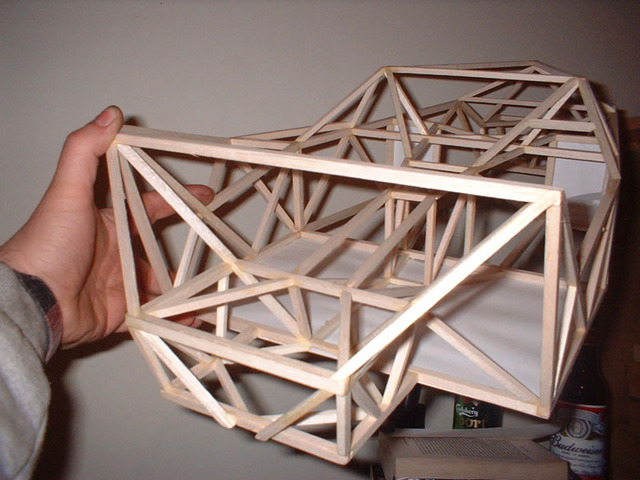
Rescued attachment chasismodel.jpg
|
|
|