flak monkey
|
| posted on 20/5/05 at 07:18 PM |

|
|
Yup, thats right.
Like I say there are many ways to come to the same conclusion, and often, one is no better than another. Neds first design has a lot of
'uneccessary' tubes (needed in that design, but not in others) which come about due to having the low sides on the chassis....swings and
roundabouts.... 
Sera
http://www.motosera.com
|
|
|
|
|
Clay
|
| posted on 20/5/05 at 07:18 PM |
|
|
what i was saying is that these two structures are equally as rigid, so the scuttle doesnt need to be supported in this design. Am I right?


Clay Marsh
|
|
|
flak monkey
|
| posted on 20/5/05 at 07:22 PM |
|
|
Yes
Sera
http://www.motosera.com
|
|
|
Clay
|
| posted on 20/5/05 at 07:25 PM |
|
|
im liking this design for if i have to have lowered sides but im still open to suggestion, this will be my first so help me out with your suggestions
everyone.
Clay Marsh
|
|
|
kreb
|
| posted on 20/5/05 at 08:09 PM |
|
|
Well the nice thing about higher sides is more side impact protection. OTOH in a typical locost your elbows would hit the structure, so you'll
have to widen things to have the sill that high.
https://www.supercars.net/blog/wp-content/uploads/2016/04/1966_FiatAbarth_1000SP1.jpg
|
|
|
Clay
|
| posted on 20/5/05 at 09:09 PM |
|
|
quote:
Originally posted by kreb
Well the nice thing about higher sides is more side impact protection. OTOH in a typical locost your elbows would hit the structure, so you'll
have to widen things to have the sill that high.
This will be considerably wider than a locost, there should be enough room between the seat and the frame for elbow room.
Clay Marsh
|
|
|
cymtriks
|
| posted on 20/5/05 at 09:50 PM |
|
|
better starting point...
If you already have a bodshell then it's a good idea to look at the chassis that originally went under it. If you copy that then the body work
wil fit straight on. If you design your own chassis then you will probably need to modify the bodywork.
The GT40 is not too far away in size or concept from the Ultima. Check out the site ultimav12.ca for an excellent set of mods for the Ultima which
result in a decent chassis perfectly adequate for your purposes.
Also try Googling for the Lotus 23 chassis and look at the Lotus 23 busa project thread on the middy section of this forum.
The Lotus 23 and the Ultima both have no tunnel down the car centre, they have sill structures instead. The tunnel on your car isn't adding
much, you may as well delete it.
A word of warning. nearly all kit car space frames are actually less stiff for their weight than simple X braced ladder frames. A ladder of
4x2-14gauge with a scuttle/footwell structure and a triangulated seat back frame would probably be as good as the frames you've discussed so
far.
I've posted some analysis results of spaceframe and ladder frame designs on the locost7.info site under files with the title
kitcaranalysisv2.doc
Good luck with the project!
|
|
|
Clay
|
| posted on 28/5/05 at 06:29 AM |
|
|
by lookin at a car that is almost identical to what im trying to do, ive noticed how they went about making the frame accessible to the driver.


for me to reduce my upper side rails to 1 low bar like they did, i would have to have a structural back bone and upper rails connecting the 2
verticals in front of and behind the driver correct?
Looking at this chassis as an engineering student, it seems like it would flex, but it seems to be working well enough here in the real world. Perhaps
I should just follow their lead and trust their engineers who certainly have much more experience at this than i do?
Clay Marsh
|
|
|
JoelP
|
| posted on 28/5/05 at 08:09 AM |
|
|
damn it i read the entire thread to see if anyone else had suggested that, and there it is in the last post!  
anyways...
the transmission tunnel is a useless waste of space and weight(see edit below). Theres no propshaft to contain, and the strength it adds could be
better added in other ways.
if you need to keep the sides low, just add bars to make a roof. This will make it much stronger and still leave space for a door.
The idea about havign a structural member in the door is pretty hard to do, its never gonna close firmly and solidly without a serious amount of work.
Unless you would bolt the door shut?!
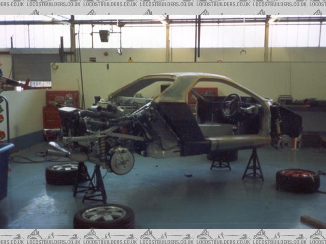
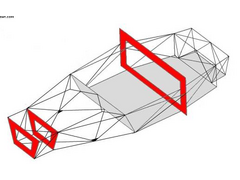
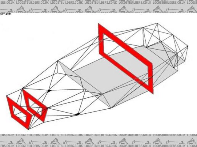
anyway, that last picture has everything you need for inspiration.
edit:
in the middle picture, you can see how the roof isnt triangulated. In this case it looks more like a roll cage than a fully functional loaded member
of the chassis. Note the remnants of the transmission tunnel, modified due to the absence of the prop, how it aims force straight through one node and
almost directly into the front suspension pickup point (and visa versa).
[Edited on 28/5/05 by JoelP]
|
|
|
britishtrident
|
| posted on 28/5/05 at 09:46 AM |
|
|
It might be worth looking at the chassis of the the Panther Solo it was based around Sierra bits and I think the design of the rear bay of the
chassis was really clever.
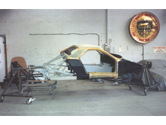 
Rescued attachment Mark_Harlow-Solo_chassis.jpg
|
|
|
britishtrident
|
| posted on 28/5/05 at 09:47 AM |
|
|
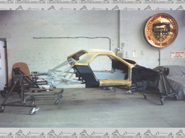
more Solo
Rescued attachment Mark_Harlow-Stage_01.jpg
|
|
|
Clay
|
| posted on 28/5/05 at 04:41 PM |
|
|
british trident, no other pictures of the panther solo?
Also, i dont see how the back bone tunnel doesnt help, if it is a rigid back bone it should help the car from bending at the middle like a V if you
are looking at the car from a side view. It's gotta offer some support.
Clay Marsh
|
|
|
JoelP
|
| posted on 28/5/05 at 04:49 PM |
|
|
it does, but not much considering its only 6inches high and wide - the same 4 bars triangulated 40 inches apart would be a lot stronger. its to do
with the distance a part is from the axis of twist or flew, the 'I' value in FEA, i believe.
[Edited on 28/5/05 by JoelP]
|
|
|
Clay
|
| posted on 28/5/05 at 05:00 PM |
|
|
i figure im going to need every bit of help i can get increasing rigidity at that mid section if im doing to reduce the outer bar to just 1 diagonal
like they did. Maybe the backbone can be improved on to be more supportive. But it looks like i will be working on a roof this week.
Clay Marsh
|
|
|
britishtrident
|
| posted on 28/5/05 at 06:48 PM |
|
|
Only 12 Solos were built info is a bit scarce.
On most cars with a backbone the backbone isn't really a main structural member -- even on Lotus road cars it was really just a subframe the
body provided a very large slice of the torsional stiffness.
[Edited on 28/5/05 by britishtrident]
|
|
|
Clay
|
| posted on 28/5/05 at 07:05 PM |
|
|
it looks like the panther solo has almost no side support members, and little to no visable overhead support.
Clay Marsh
|
|
|
tks
|
| posted on 28/5/05 at 07:48 PM |
|
|
mhhhh
i have also some ideas...
building a space frame chasis is also playing the game with space efficienty...
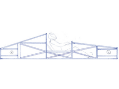
If you see my pic you see the bar going to the top wich on geeting in the car would harm you and i'm pretty sure it will increase the
stiffness
also think you can use some 4mm sheet...
it will not help the forces sidewards....but the flex just up and down will be eliminated if used on the good places with good amounts..
TKS
as you see i have now moved the weakest point more forwards.in the chasis....
anyway this is the typical reason wy a cabrio is more expensive to a normal car one..the desing is much different....
if you can live with the tubes arround your head..it will eliminate allot of tubes on the side...(not mentioning the ones for side impact..)
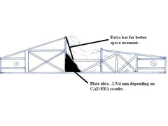 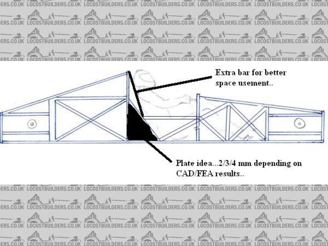
Rescued attachment nedchassis1.jpg
The above comments are always meant to be from the above persons perspective.
|
|
|
JoelP
|
| posted on 28/5/05 at 07:59 PM |
|
|
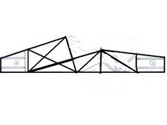
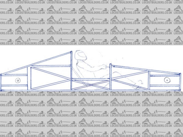
this is my take of it. obviously its only a 2d thing, wouldnt be a direct switch to 3d.
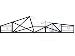 
Rescued attachment schmia1.JPG
|
|
|
tks
|
| posted on 28/5/05 at 09:51 PM |
|
|
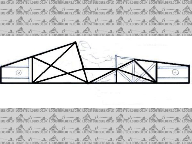
yes
it would be the lihgtes option i have seen
but i stil would add one bar..
from the scuttle backwards...
SPACE USEMENT..
Tks
The above comments are always meant to be from the above persons perspective.
|
|
|
JoelP
|
| posted on 29/5/05 at 09:43 AM |
|
|
if you could afford the space, that would be much stronger.
ps, if i ever modify this piccy again, i will add the front and back suspension pickup points in, so i can try to like the two together well. big red
dot or something.
[Edited on 29/5/05 by JoelP]
 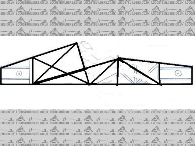
Rescued attachment schmia1.JPG
|
|
|
Liam
|
| posted on 30/5/05 at 11:13 PM |
|
|
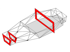
Nice, but I wouldn't like to make it
Keeping the original shape, wouldn't this be simplest. All triangles...
Liam
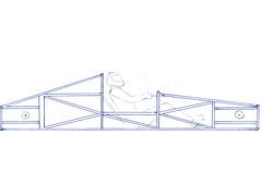 
Rescued attachment frame.jpg
|
|
|
Liam
|
| posted on 30/5/05 at 11:17 PM |
|
|
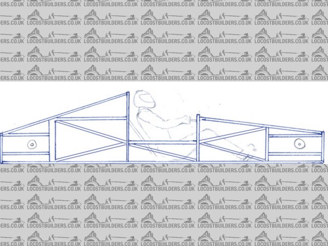
Actually i'd be tempted to cross the sill cos being so low it will be highly stressed...
Rescued attachment frame.jpg
|
|
|
cymtriks
|
| posted on 1/6/05 at 06:23 PM |
|
|
quote:
Originally posted by me!
If you already have a bodshell then it's a good idea to look at the chassis that originally went under it. If you copy that then the body work
wil fit straight on. If you design your own chassis then you will probably need to modify the bodywork.
The GT40 is not too far away in size or concept from the Ultima. Check out the site ultimav12.ca for an excellent set of mods for the Ultima which
result in a decent chassis perfectly adequate for your purposes.
Also try Googling for the Lotus 23 chassis and look at the Lotus 23 busa project thread on the middy section of this forum.
The Lotus 23 and the Ultima both have no tunnel down the car centre, they have sill structures instead. The tunnel on your car isn't adding much,
you may as well delete it.
A word of warning. nearly all kit car space frames are actually less stiff for their weight than simple X braced ladder frames. A ladder of
4x2-14gauge with a scuttle/footwell structure and a triangulated seat back frame would probably be as good as the frames you've discussed so
far.
I've posted some analysis results of spaceframe and ladder frame designs on the locost7.info site under files with the title
kitcaranalysisv2.doc
Good luck with the project!
And take a look at this---
Rescued attachment frame23_pbh.JPG
|
|
|
JoelP
|
| posted on 1/6/05 at 09:31 PM |
|
|
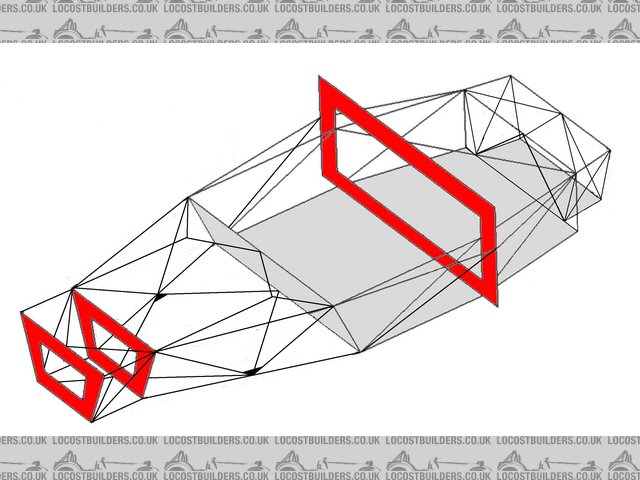
one that can be seen without borrowing NASAs array of monitors
Rescued attachment untitledcy1.jpg
|
|
|


